Download
1 / 26
260 likes | 370 Vues
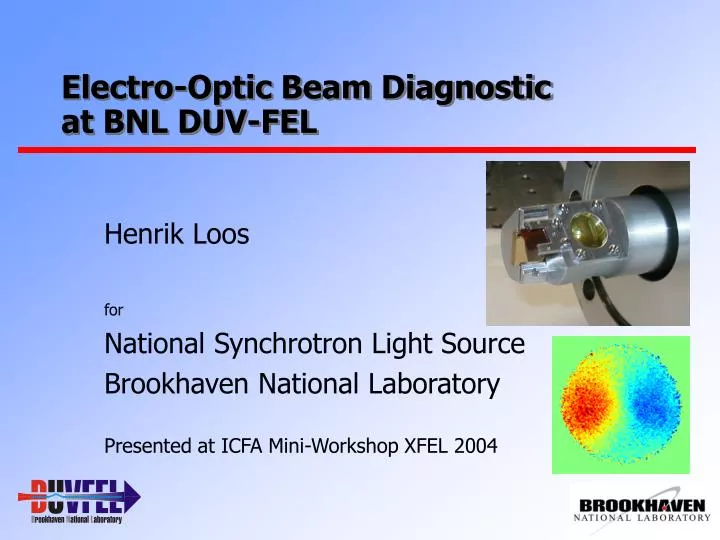
Electro-Optic Beam Diagnostic at BNL DUV-FEL. Henrik Loos for National Synchrotron Light Source Brookhaven National Laboratory Presented at ICFA Mini-Workshop XFEL 2004. Outline. DUV-FEL accelerator facility Coulomb field measurement THz CTR pulse characterization

E N D
Electro-Optic Beam Diagnostic at BNL DUV-FEL Henrik Loos for National Synchrotron Light Source Brookhaven National Laboratory Presented at ICFA Mini-Workshop XFEL 2004
Outline • DUV-FEL accelerator facility • Coulomb field measurement • THz CTR pulse characterization • Issues for ultrafast electro-optic measurement • Summary and outlook
DUV-FEL Facility FEL seed at 800 nm Normal incidence 177 Modulator Nisus Wiggler 77 MeV MeV Undulator Adjustable CTR Monitor Dispersion NISUS pop-in Ion Pair Imaging Photoinjector Chicane Magnet RF zero Phasing monitors Experiment Trim Chicane at 88 nm 30 mJ Ti:Sapphire Amplifier FEL Measurements Energy, Spectrum, Synchronization and Pulse Length Measurements at 266 nm 50 m Radiator (NISUS) Wiggler: L = 10 m, lw = 3.89 cm B = 0.31 T, K = 1.126 HGHG: 100 µJ @266 nm 3rd harm. 1 µJ @89 nm
Electro-Optic Bunch Diagnostic Delay Multi-Shot Laser e-Beam E-Field Single-Shot Laser ZnTe • Uses Pockels-effect to detect electric field E of Coulomb field or THz radiation with fs laser. • Birefringence in <110> cut ZnTe with E-field and laser polarization to [001] axis • Detect change in laser polarizationwith l/4 waveplate and analyzer. • Signal asymmetry A between linear polarization states gives phase change.
Experimental Setup Laser Electrons • Constants:l= 800 nm n0 = 2.83r41= 4 pm/V e = 10l = 0.5 mm • Dj = 90o at 170 kV/cm
Single Shot Time Calibration • Ti:Sa chirped to 6 ps. • e-beam ~1ps FWHM. • Laser delay changed from 0.5 to –1.0 mm • Strong modulation in spectrum from uncoated ZnTe crystal. • Average of 50 single shot spectra. • Charge from Coulomb field lower than ‘real’ charge of 250 pC. Ds = 0.5 mm, Q = 130 pC Ds = 0 mm, Q = 80 pC Ds = -0.5 mm, Q = 125 pC Ds = -1.0 mm, Q = 130 pC
Time resolution • Minimum THz pulse length with 6 ps, 6 nm chirped laser • Distance e-beam/laser (850 µm) • Monochromator (1800/mm) grating is 30 fs. • Coherence length in ZnTe (500 µm thick) is 200 fs. • Measured length of 1.6 ps dominated by spectral distortion and confirmed by simulation.
Jitter Measurement 25 20 15 Pulse # (s) 10 5 -5 0 5 10 Time (ps) 10 s = 167 fs 5 0 -600 -400 -200 0 200 400 600 Delay (fs) • Single shot enables jitter measurement. • Spectral distortions do not affect centroid position. • 50 shots = 25 s. • Jitter e-beam/seed laser 170 fs. • Jitter low-level RF/Ti:Sa 200 fs. • Energy jitter after bend magnet equals 1 ps rf phase jitter mostly rf amplitude jitter. • Use for feedback on laser phase. Head Tail
THz Pulse Field Characterization • 80 µJ CTR pulse observed at DUV-FEL. • E-beam 700 pC, 100 MeV, 150 (???) fs rms. • Measure spatial-temporal electric field distribution with EO sampling. • Understand relay and focusing of CTR. • Compare with CTR simulation code. • Compare with bolometer measurement.
Electro-Optic THz Radiation Setup Electron Beam Vacuum Window Paraboloid f = 7.5” f = 1.5” Delay Polarizer ZnTe Analyzer CCD Ti:Sa Laser Coupling Hole, 2 mm l/4 Lens
Signal and Reference OAP ZnTe l/4 Pol. Ref Signal BS Camera
Image Processing for Field Measurement -2 100 -1 200 Pixels Vertical (mm) 0 300 1 400 2 100 200 300 400 500 600 -2 -1 0 1 2 Pixels Horizontal (mm) • Use compensator waveplate to detect sign of polarization change. • Reference IR (left) and Signal IS (right) obtained simultaneous. • Rescale and normalize both. • Calculate asymmetry A of Signal. • Subtract asymmetry pattern w/o THz. A = 2IS/IR - 1
Time Dependent Measurement • Use ‘mildly’ compressed bunch of 500 fs rms and 300 pC to get both 0-phasing and electro-optic measurement. • Temporal scan by varying phase of accelerator RF to both sample and cathode laser. • Approximately equivalent to varying delay between both lasers but much faster and computer controlled. • Measured to be 1.2 ps/degree.
Transverse-Temporal Distribution Image asymmetry 0.5 1 Horizontal pos. (mm) 0 0 -1 -0.5 -1 0 1 2 Time (ps) • Take horizontal slice through images. • Asymmetry of 1 equals 170 kV/cm electric field strength. • Charge 300 pC. • Saturation and ‘over-rotation’ at higher compression. • Needs crystal « 500 mm.
Simulation of CTR Propagation • Decompose radiating part of coulomb field in Gauss-Laguerre modes. • Calculate transmission amplitude and phase through experiment for THz spectral range. • Use bunch form factor to reconstruct radiation field in time and space. • Example: 300 pC, 300 fs 30 mm 20 ps
Focus Distribution of THz • Focus spot size3 mm diameter. • Single cycle oscillation. • 300 fs rms length. • Electric field strength more than 300 kV/cm at 300 pC charge. • Pulse Energy 4 mJ.70 mJ (700 pC, 150 fs)
Simulation vs. Experiment Experiment Simulation/2 • Simulation gives 2 times more field. • Tighter focus in simulation. • Up to 50 kV/cm measured.
Single Cycle THz Pulses • Pulse energy from field ~60 nJ. • Pulse energy with Joule-meter 170 nJ. • Pulse energy from simulation 800 nJ. • Good match of temporal and spectral properties. • Factor 2 and 4 difference in field and energy. • Measured 80 mJ to have 1 MV/cm field in focus.
THz Spectrum • Present intensity limited by geometric apertures. • Low frequency cutoff at 15 cm-1 or 0.5 THz.
Potential Ultrafast EO-Detection • Intense ultrafast THz source. Modulated electron beam (@DUV-FEL). High pulse energy CTR (C...R). • Broadband, uniform response EO-material. EO-Polymer Composites. • Time domain laser pulse measurement. Amplified fs-laser (injector drive laser). Spectral phase measurement. FROG, SPIDER. Not limited by laser pulse length.
Modulated Beam Studies 70 MeV 180 pC 20 50 E (keV) 0 25 -20 D 0 -3 -1.5 0 1.5 3 Energy (keV) 200 -25 -50 Current (A) -3 -1.5 0 1.5 3 0 -3 -1.5 0 1.5 3 Time (ps) Time (ps) • ~100 fs e-beam structures from modulated drive laser. • Measured with longitudinal tomography. • Use to test electro-optic resolution, can be further compressed.
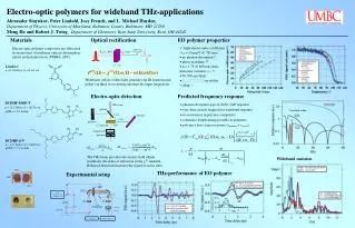
Broadband Electro-Optic Materials • EO-polymers* have 20x larger EO-coefficient than ZnTe. • No phonon resonances in far-IR. • Phase mismatch. • Lifetime ~weeks. • 10 µm sufficient. • Cooling? * 20% DCDHF-6-V/20% DCDHF-MOE-V/60% APC A.M. Sinyukov, L.M. Hayden, to be published
Measuring the Spectral Phase: SPIDER Spectral Phase Interferometry for Direct Electric-Field Reconstruction (Walmsley group, Oxford) 400 nm 800 nm 800 nm Mix 2 replicas from EO-modified pulse with original streched pulse.
Summary and Outlook • Simple single shot chirped EO setup sufficient for jitter measurement. • Jitter of 170 fs equal to low-level rf/laser jitter and estimates from HGHG. • Enables noninvasive laser/e-beam synchronization-feedback. • Ultrafast EO measurement requires time-domain method. • High intensity THz pulses up to 1 MV/cm field strength from CTR. • CTR simulation, pulse energy and electro-optic measurement in resonable agreement. • Extract THz to accessible user station for various applications. • Use time-domain single-shot EO method and apply to THz from modulated electron beam.
Acknowledgements SDL/DUV-FEL Team G.L. Carr J. Greco H. Loos† J.B. Murphy J. Rose T.V. Shaftan B. Sheehy Y. Shen B. Singh X.J. Wang Z. Wu L.H. Yu † In future at SLAC This work was supported by DOE Contracts DEAC No. DE-AC02-98CH10886 and AFOSR/ONR MFEL Program No. NMIPR01520375.