DAF System
DAF System. Air Supply Pressurizing Pump Retention Tank Flotation Chamber. SKEMATIK PROSES DAF. DAF Configuration. Full Flow Pressurization Partial Flow Pressurization Recycle Flow Pressurization. Full Flow Pressurization.

DAF System
E N D
Presentation Transcript
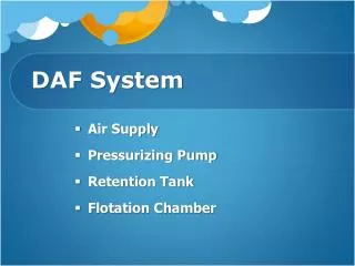
DAF System • Air Supply • Pressurizing Pump • Retention Tank • Flotation Chamber
DAF Configuration • Full Flow Pressurization • Partial Flow Pressurization • Recycle Flow Pressurization
Full Flow Pressurization • The entire influent feed stream is pressurized by a pressurizing pump and held in the retention tank • The system is usually applicable to the feed stream with suspended solids exceeding 800 mg/L in concentration • It is not susceptible to the shearing effects caused by the pressurizing pump and the high pressure drop at the pressure release valve • Suspended solids will flocculate rapidly with the addition of chemical coagulants in the inlet compartment in the presence of the released air
Partial Flow Pressurization • Only about 30–50% of the influent feed stream is pressurized by a high-pressure pump and held in the retention tank. • Materials with low specific gravity can be removed with the partial flow pressurization system. • The increased hydraulic flow on the flotation chamber due to the flow recirculation must be taken into account in the flotation chamber design.
Recycle Flow Pressurization • A portion (15–50%) of the clarified effluent from the flotation chamber is recycled, pressurized, and semisaturated with air in the retention tank. • The system is usually employed in applications where preliminary chemical addition and flocculation are necessary ahead of flotation. • This system is not recommended for use when the suspended solids are susceptible to the shearing effects of the pressurizing pump and the high-pressure drop at the pressure release valve. • The suspended solids concentrations are low.
Faktor-Faktor Yang MempengaruhiKinerja DAF • SifatPartikel • UkuranPartikel • Dispersing Agents • Komposisidansifat Influent • ArusCairan • Rasio A/S • Float Removal
SifatPartikel • The specific gravity is a characteristic of the particle or liquid to be abated or separated. • It can easily be accepted that sand, for example, cannot be floated while voluminous material, such as activated sludge, or a water immiscible liquid such as oil, can be floated.
UkuranPartikel • Generally, floatability increases with the size of the particle. • In many cases,thesize of particles can be increased by flocculation with various chemical coagulants.
Dispersing Agents • Certain wastewaters and liquids contain unusual concentrations of various chemicals, resulting in specific flotation problems or advantages. • Surfactants, such as detergents, tend to alter the physical properties of the sludge particle surface to be floated.
Komposisidansifat Influent • The composition and nature of the influent is most important. • Equalization of composition and flow improves the performance of the flotation unit.
ArusCairan • The liquid currents are governed by the physical design and hydraulics of the flotation unit. • This becomes a consideration in the design of the tank and hydraulic loadings of the flotation unit.
Rasio A/S • The amount of air and the method of mixing the air with the material to be floated are functions of the design of a particular flotation unit. • For a specific application, a definite amount of air is necessary for flotation. • In thickening applications it has been shown that increased performance is obtained at higher A/S ratios.
Float Removal • A float-removal mechanism must be designed to have adequate capacity to remove water carryover. • Various items to be considered in this design are the depth of submergence of the scooping mechanism and the speed of scoop operation.
Gas to Solids Ratio : Full Flow Pressurized System G Gin Gout Q Cf X Q Cr Q Ce G Correction factor, F or f, because complete gas saturation of liquid is often not achieved in a pressurized retention tank F = 0,5 – 1,0 P ≥ 2 atm P < 2 atm f = 0,167 – 1,0 Henry’s law
Gas to Solids Ratio : Partial Flow Pressurized System Q Cf X G Qn Cf Gin Gout Q Ce Qp Cr G F = 0,5 – 1,0 P ≥ 2 atm P < 2 atm f = 0,167 – 1,0 The Qp/Q ratio ranges between 0.3 and 0.5
Gas to Solids Ratio : Partial Flow Pressurized System G Q Cf X Q Ce Gout Gin Qr Cr G F = 0,5 – 1,0 P ≥ 2 atm R = Qr/Q P < 2 atm f = 0,167 – 1,0
Design Parameters • Hydraulic loading rate • Solids loading rate • Air to Solids ratio • Retention Tank Pressure
Basic Design Concept The ratio of Q/As is also defined as the hydraulic loading rate VH = horizontal velocity (m/s), Q = influent flow rate (m3/s), Ac = cross-sectional area of a flotation chamber (m2) VT = vertical rise rate of suspended solids (m/s), D = effective depth of the flotation chamber (m), T = detention time (s), Q = influent flow rate (m3/s), AS = surface area of flotation chamber (m2)
Basic Design Concept D = effective depth (m) W = effective width (m) L = effective length (m) • The D/W ratio is usually between 0.3 and 0.5 • F′= factor for short circuiting and turbulence, assumed as 1.4.