Download

1 / 21
230 likes | 543 Vues
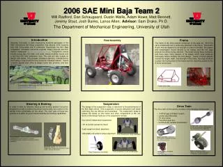
Suspension Modeling and Numerical Analysis for a SAE Baja Vehicle. Chris Eaton & Dan Schwarz. SAE Baja Design Competition. Design and build a vehicle to survive the punishment of rough terrain Powered by Briggs and Stratton Intek Model 20 Engine

E N D
Suspension Modeling and Numerical Analysis for a SAE Baja Vehicle Chris Eaton & Dan Schwarz
SAE Baja Design Competition • Design and build a vehicle to survive the punishment of rough terrain • Powered by Briggs and Stratton Intek Model 20 Engine • Compete with universities from around the world • Three regional competitions with a variety of events • Static events including design review, sales presentation • Dynamic events including mud bog, rock crawl, chain pull • Four hour endurance race
Laker Racing Standings 2007 45th Place Overall 2008 29th Place Overall
Past Performance Breakdown Cost – 66/100 pts Design – 121/175 pts Acceleration – 60/75 pts Maneuverability – 38/75 pts Pull – 57/75 pts Suspension – 48/75 pts Endurance – 296/400 pts Technical penalty – (50) pts Overall – 638/1000 pts
Problem Statement • Excessive vertical displacement of vehicle frame • Excessive frame roll in cornering • Heavier spring rates?
Simplified Suspension Model • Vehicle is modeled as a mass-spring-damper system • System has front and rear wheel inputs • System was analyzed through energy balance equations
Simplified Suspension Model • The energy balance equations were used to derive two differential equations for vertical and angular motion • These two second order equations were converted into a system of eight first order differential equations
Suspension Geometry & Spring Rates • Due to the compound angle of the coil-over-shocks the spring rate in the vertical plane needed to be found • The original spring rates and two test spring rates were evaluated • The maximum input force exerted on the system was assumed to be 600lb
Forcing Functions • The amplitude of the forcing function was determined by the displacement of the springs with a 600lb load • The vehicle was assumed to be traveling 10 mph or 176 in/s over the obstacles • It was assumed that the obstacles were spaced one wheel base length apart (56”) • Therefore, the input frequency should be approximately 3 hz
Selection of Analysis Method • Euler's method was used to generate solutions • This method was chosen for the ease of implementation • Only 0.001” of accuracy was deemed to be necessary for the solutions • The greatest magnitude of error was calculated to be 0.00041” with a step width of 1 millisecond • Therefore, Euler's method was sufficient
System Response to Bump Input • Each system was subjected to a 600lb bump input • The rear tire collided with the bump approximate 0.33 sec after the front tire
System Response to Sine Input • Each system was subjected to a 600lb sinusoidal input
Suspension Resonance Conditions • The natural frequency of the original system was approximately 12.5 hz • Resonance occurs when the suspension is subjected to a 600lb sinusoidal input with the natural frequency, no damping, and no phase shift between the front and rear wheel inputs
Conclusions • Case 1 (softest spring rates) will produce the greatest ride comfort • Case 3 (stiffest spring rates) will produce the best resistance to bounce and pitch • The system will most likely not be subjected to the natural frequency for the amount of time required to produce significant resonance