Download
1 / 22
220 likes | 223 Vues
This research paper discusses the development of a terrestrial antenna-based GW detector using superconducting instrumentation to fill the missing bandwidth in the 0.1 to 10 Hz range. The paper explores different detector options, noise mitigation techniques, and suspension methods.

E N D
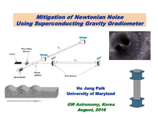
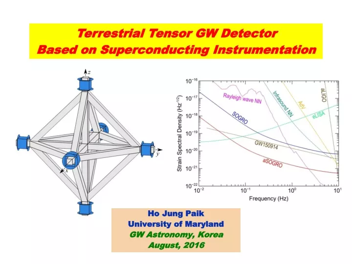
Terrestrial Tensor GW Detector Based on Superconducting Instrumentation Ho Jung PaikUniversity of MarylandGW Astronomy, Korea August, 2016
GW detector bandwidths Missing frequency band • Merger of IMBHs and inspiraling stellar mass BHs are expected to produce signals at 0.1 to 10 Hz bandwidth. • Even if LISA flies, the middle frequency band will be missed. DECIGO, space interferometer, has been proposed to fill this band. • Could a terrestrial antenna be built to fill this missing band? Paik
Long-baseline resonant-mass detector • In the Newtonian limit, Gravity gradiometer is a GW detector. Paik
Analyzed three detector options: 1. Atom-laser interferometer 2. TOBA with laser interferometer 3. Michelson interferometer • Low-frequency detector would be astrophysically interesting, if one can reach Sh½(f ) = 1020 Hz1/2in 0.1-10 Hz band. Paik
Newtonian gravity noise • Seismic and atmospheric density modulations cause Newtonian gravity gravity gradientnoise (NN). • At 0.1 Hz, s ~ 35 km >> L. Gravity gradient noise L. Newtonian noise (NN) Rayleigh wave NN residual Infrasound NN subtraction • Need to develop more sensitive seismometers and microphones. • NN from infrasound can be mitigated only at certain incident angles. Detecting and removing NN appears to be extremely challenging. Paik
SGG (Superconducting Gravity Gradiometer) • Sensitive SGGs have been under development for over 30 years at UM. 3 x 10-11 Hz-1/2 Moody et al., RSI 73, 3957 (2002) • Test masses are mechanically suspended (fDM ~ 10 Hz). • CM platform vibration noise is rejectedto 3 parts in 108. • By early 1990’s, SGG achieved amplitude sensitivity 102 times better than TOBA and 103 times better than atom interferometers to date. Paik
Tensor SGG with levitated test masses • More sensitive SGG is under development with NASA support. • Test masses are magnetically suspend (fDM ~ 0.01 Hz). 102-103 times higher sensitivity Test masses are levitated by a current induced along a tube. Six test masses mounted a cube form a tensor gradiometer. Paik
Improved CM rejection • Sensitive axes are aligned to 10-6 rad insituusing Cryo Linear Actuator PiezoKnobs (Janssen Precision Eng). CMRR = 106 • Residual CM errors are compensated to 10-4. CMRR = 1010 Intrinsic noise of the SGG for Earth science mission Paik
+ polarization x polarization SOGRO (Superconducting Omni-directional Gravitational Radiation Observatory) • Each test mass has 3 DOF. • Combining six test masses, tensor GW detector is formed. • Source direction (, ) and wave polarization (h+, h) can be determined by a single antenna. “Spherical” Antenna Paik
Antenna pattern LIGO Sky location of GW150914 polarization +polarization rms sensitivity SOGRO Total Sky location by SOGRO Off-diagonal Diagonal Paik
Design philosophy of SOGRO • Extremely low detector noise is required. Low T, high Q, nearly quantum-limited amplifier. • Test mass suspension frequency should be lowered to below the signal bandwidth. Almost free test masses by magnetic levitation. • Seismic noise is very difficult to isolate at low frequencies. HighCM rejection in a superconducting differential accelerometer. • Newtonian noise increases sharply below 10 Hz and cannot be shielded. Tensordetector can help mitigate the NN. H. J. Paik, C. E. Griggs, M. V. Moody, K. Venkateswara, H. M. Lee, A. B. Nielsen, E. Majorana and J. Harms, Class. Quantum Grav. 33, 075003 (2016) Paik
Suspension of SOGRO platform • Go underground(~ 1 km) to reduce the seismic and Newtonian noise, as well as to be far away from moving objects. • Platform needs to be rigid with all DM modes > 10 Hz with Q > 106. Careful engineering design is required. • Nodal support prevents odd harmonics from being excited. • 25-m pendulum gives fp = 0.1 Hz for two horizontal modes and f < 103 Hz for torsional angular mode, and completely decouples ground tilt. Provides passive isolation. • Additional passive or active isolation may be needed for vertical direction. Pendulum suspension from center Alternative suspension: Optical rigid body Simpler cryogenics, larger baseline ( 1 km?) Paik
Magnetic levitation • To provide large area for levitation, test mass is made in the shape of square Nb shell with flanges. • Magnetic field required to levitate test mass: • Horizontal DM frequencies can all be tuned to 0.01 Hz. • However, due to nonlinearities, strong levitation fields will cause vertical DM frequencies > 0.1 Hz. Vertical accelerometers will be noisier. • Since the platform is isolated from tilt of the ground,hxz and hyz can also be obtained from horizontal motions of test masses only. Paik
Tuned capacitor-bridge transducer • Near quantum-limited SQUIDs have 1/f noise below 10 kHz. • Signal needs to be upconverted to 10 kHz by using active transducer. • Capacitor bridge coupled to nearly quantum-limited SQUID thru S/C transformer. (Cinquegrana et al., PRD 48, 448 (1993)) • Bridge is driven at LC resonance frequency p . • Oscillator noise is rejected by the bridge balance. Maintain precise balance byfeedback. Paik
Achievable detector noise • SOGRO requires QD ~ 109 for test masses and Qpl ~ 107 for the platform. • By using two-stage dc SQUIDs, 120 and 10 have been demonstrated at 1.5 and 0.1 K, respectively. (Falferi et al., 2003; 2008) SOGRO requires improvement by a factor of 5-6. Paik
Potential sensitivities of SOGRO • SOGRO would fillfrequency gap 0.1 to 10 Hz between the terrestrial and future space interferometers. Paik
Platform thermal noise • Internal damping model: Thermal displacement noise PSD becomes where M is the effectivemassof the platform and Q = 1/. • Desirable to locate test masses at nodesof the mode, M . Very challenging due to the presence of multiple modes • Platform design needs to be optimizedto minimize its thermal noise. Preliminary analysis with ANSYS Paik
Astrophysics with SOGRO • SOGRO could detect IMBH binaries with 103-104M◉ at a few billion light years away, and WD binaries within the Local Group. • aSOGRO would be able to detect BH binaries like GW150914 with SNR ~ 10. Alert interferometers days before merger. Paik
Seismic noise At 1 Hz Seismic background Axis alignment and scale factor match Error compensation SOGRO intrinsic noise aSOGRO intrinsic noise Passive/active isolation 109 1010 1011 1012 1013 1014 1015 1016 1017 1018 1019 1020 Seismic noise of underground sites Amplitude noise level (m Hz1/2) • 200-220 dB isolation/rejection is required. • CMRR = 1010 0-20 dB isolation required. • Pendulum suspension provides sufficient passive isolation for angular and horizontal accelerations. • 0-20 dB passive/active isolation must be provided to vertical acceleration. Paik
Newtonian gravity noise • Seismic and atmospheric density fluctuations produce NN. • GWs are transversewhereas near-field Newtonian gradient is not. Could GW signal be separated out from NN? • Tensor measurement is insufficient to remove NN from multiple waves. Still requires external seismometers and microphones. Paik
Mitigation of NN NN due to infrasound removed by using h’13, h’23, h’33 and 15 mikes of SNR = 104, 1 at the detector, 7 each at radius 600 m and 1 km. NN due to Rayleigh waves removed by using h’13, h’23, h’33, az (CM), plus 7 seismometers with SNR = 103 at the radius of 5 km. • First remove Rayleigh NN by using seismometers only, then remove infrasound NN by using microphones and cleaned up SOGRO outputs. • Unlike TOBA and laser interferometer, SOGROcan remove NN from infrasound for all incident angles. Harms and Paik, PRD 92, 022001 (2015) Paik
Conclusion and summary • By using six levitated superconducting test masses, low-frequency tensor GW detector can be constructed. A single SOGRO could locate source and determine polarization. • SOGRO is uniquely capable of CM rejection and full-tensordetection. SOGRO couldovercome the seismic and Newtonian noise. • With h 1020 Hz1/2 at 0.1-10 Hz, SOGRO could detect IMBH binaries at a few billion light years away, as well as BH binaries like GW150914. SOGRO could alert laser interferometers days before merger. • Test masses of 5-10 tons each and 3D platform of arm-length 30-100 m(100-300 tons) need to be cooled to below 4 K. Large-scale civil, mechanical, and cryogenic engineering is required. • Very high Q’s must be obtained for test masses and platform, and nearly quantum-limited transducer-SQUID system must be developed. Materials science and detector technology must be advanced. SOGRO is a multi-disciplinary project like LIGO, Virgo and KAGRA. Paik