E-R Model
E-R Model. A database can be modeled as: a collection of entities, relationship among entities. An entity is an object that exists and is distinguishable from other objects. Example: specific person, company, event, plant Entities have attributes

E-R Model
E N D
Presentation Transcript
E-R Model • A database can be modeled as: • a collection of entities, • relationship among entities. • An entityis an object that exists and is distinguishable from other objects. • Example: specific person, company, event, plant • Entities have attributes • Example: people have names and addresses • An entity set is a set of entities of the same type that share the same properties. • Example: set of all persons, companies, trees, holidays
Entity Sets customer and loan cust_idcust_namecust_ streetcust_ no loan_no amount
Relationship Sets • A relationship is an association among several entities Example:HayesdepositorA-102customer entity relationship set account entity • A relationship set is a mathematical relation among n 2 entities, each taken from entity sets {(e1, e2, … en) | e1 E1, e2 E2, …, en En}where (e1, e2, …, en) is a relationship • Example: (Hayes, A-102) depositor
Relationship Sets (Cont.) • An attribute can also be property of a relationship set. • For instance, the depositor relationship set between entity sets customer and account may have the attribute access-date
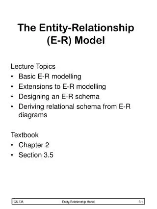
Attributes • An entity is represented by a set of attributes, that is descriptive properties possessed by all members of an entity set. Example: customer = (customer_id, customer_name, customer_street, customer_city) loan = (loan_number, amount ) • Domain – the set of permitted values for each attribute • Attribute types: • Simple and composite attributes. • Single-valued and multi-valued attributes • Example: multivalued attribute: phone_numbers • Derived attributes • Can be computed from other attributes • Example: age, given date_of_birth
Composite and Multivalued Attributes • Composite attributes are flattened out by creating a separate attribute for each component attribute • Example: given entity set customer with composite attribute name with component attributes first_nameand last_name the schema corresponding to the entity set has two attributesname.first_name and name.last_name • A multivalued attribute M of an entity E is represented by a separate schema EM • Schema EM has attributes corresponding to the primary key of E and an attribute corresponding to multivalued attribute M • Example: Multivalued attribute dependent_names of employee is represented by a schema:employee_dependent_names = (employee_id, dname) • Each value of the multivalued attribute maps to a separate tuple of the relation on schema EM • For example, an employee entity with primary key 123-45-6789 and dependents Jack and Jane maps to two tuples: (123-45-6789 , Jack) and (123-45-6789 , Jane)
Mapping Cardinality Constraints • Express the number of entities to which another entity can be associated via a relationship set. • Most useful in describing binary relationship sets. • For a binary relationship set the mapping cardinality must be one of the following types: • One to one • One to many • Many to one • Many to many
Mapping Cardinalities One to one One to many
Mapping Cardinalities Many to one Many to many
Cardinality Constraints • We express cardinality constraints by drawing either a directed line (), signifying “one,” or an undirected line (—), signifying “many,” between the relationship set and the entity set. • One-to-one relationship: • A customer is associated with at most one loan via the relationship borrower • A loan is associated with at most one customer via borrower
One-To-Many Relationship • In the one-to-many relationship a loan is associated with at most one customer via borrower, a customer is associated with several (including 0) loans via borrower
Many-To-One Relationships • In a many-to-one relationship a loan is associated with several (including 0) customers via borrower, a customer is associated with at most one loan via borrower
Many-To-Many Relationship • A customer is associated with several (possibly 0) loans via borrower • A loan is associated with several (possibly 0) customers via borrower
Alternative Notation for Cardinality Limits • Cardinality limits can also express participation constraints
Participation of an Entity Set in a Relationship Set • Total participation (indicated by double line): every entity in the entity set participates in at least one relationship in the relationship set • E.g. participation of loan in borrower is total • every loan must have a customer associated to it via borrower • Partial participation: some entities may not participate in any relationship in the relationship set • Example: participation of customer in borrower is partial
E-R Diagrams • Rectangles represent entity sets. • Diamonds represent relationship sets. • Lines link attributes to entity sets and entity sets to relationship sets. • Ellipses represent attributes • Double ellipses represent multivalued attributes. • Dashed ellipses denote derived attributes. • Underline indicates primary key attributes (will study later)
E-R Diagram With Composite, Multivalued, and Derived Attributes
Roles • Entity sets of a relationship need not be distinct • The labels “manager” and “worker” are called roles; they specify how employee entities interact via the works for relationship set. • Roles are indicated in E-R diagrams by labeling the lines that connect diamonds to rectangles. • Role labels are optional, and are used to clarify semantics of the relationship
Converting Non-Binary Relationships to Binary Form • In general, any non-binary relationship can be represented using binary relationships by creating an artificial entity set. • Replace R between entity sets A, B and Cby an entity set E, and three relationship sets: 1. RA, relating E and A 2.RB, relating E and B 3. RC, relating E and C • Create a special identifying attribute for E • Add any attributes of R to E • For each relationship (ai , bi , ci) in R, create 1. a new entity eiin the entity set E 2. add (ei , ai) to RA 3. add (ei , bi) to RB4. add (ei , ci) to RC
Weak Entity Sets • An entity set that does not have a primary key is referred to as a weak entity set. • The existence of a weak entity set depends on the existence of a identifying entity set • it must relate to the identifying entity set via a total, one-to-many relationship set from the identifying to the weak entity set • Identifying relationship depicted using a double diamond • The discriminator(or partial key) of a weak entity set is the set of attributes that distinguishes among all the entities of a weak entity set. • The primary key of a weak entity set is formed by the primary key of the strong entity set on which the weak entity set is existence dependent, plus the weak entity set’s discriminator.
Weak Entity Sets (Cont.) • We depict a weak entity set by double rectangles. • We underline the discriminator of a weak entity set with a dashed line. • payment_number – discriminator of the payment entity set • Primary key for payment – (loan_number, payment_number)
Extended E-R Features: Specialization • Top-down design process; we designate subgroupings within an entity set that are distinctive from other entities in the set. • These subgroupings become lower-level entity sets that have attributes or participate in relationships that do not apply to the higher-level entity set. • Depicted by a triangle component labeled ISA (E.g. customer “is a” person). • Attribute inheritance – a lower-level entity set inherits all the attributes and relationship participation of the higher-level entity set to which it is linked.
Extended ER Features: Generalization • A bottom-up design process – combine a number of entity sets that share the same features into a higher-level entity set. • Specialization and generalization are simple inversions of each other; they are represented in an E-R diagram in the same way. • The terms specialization and generalization are used interchangeably. • Can have multiple specializations of an entity set based on different features. • E.g. permanent_employeevs. temporary_employee, in addition to officer vs. secretary vs. teller • Each particular employee would be • a member of one of permanent_employeeor temporary_employee, • and also a member of one of officer, secretary, or teller • The ISA relationship also referred to as superclass - subclassrelationship
Aggregation • Consider the ternary relationship works_on, which we saw earlier • Suppose we want to record managers for tasks performed by an employee at a branch
Aggregation (Cont.) • Relationship sets works_onand manages represent overlapping information • Every manages relationship corresponds to a works_on relationship However, some works_on relationships may not correspond to any manages relationships • So we can’t discard the works_on relationship • Eliminate this redundancy via aggregation • Treat relationship as an abstract entity • Allows relationships between relationships • Abstraction of relationship into new entity • Without introducing redundancy, the following diagram represents: • An employee works on a particular job at a particular branch • An employee, branch, job combination may have an associated manager
E-R Design Decisions • The use of an attribute or entity set to represent an object. • Whether a real-world concept is best expressed by an entity set or a relationship set. • The use of a ternary relationship versus a pair of binary relationships. • The use of a strong or weak entity set. • The use of specialization/generalization – contributes to modularity in the design. • The use of aggregation – can treat the aggregate entity set as a single unit without concern for the details of its internal structure.