Download
1 / 37
370 likes | 688 Vues
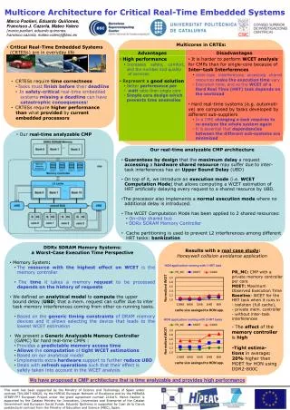
Twelve Principles for the Design of Safety-Critical Real-Time Systems. H. Kopetz TU Vienna April 2004. Outline. Introduction Design Challenges The Twelve Design Principles Conclusion. Examples of Safety Critical Systems--No Backup .

E N D
Twelve Principles for the Design of Safety-Critical Real-Time Systems H. Kopetz TU Vienna April 2004
Outline • Introduction • Design Challenges • The Twelve Design Principles • Conclusion
Examples of Safety Critical Systems--No Backup • Fly-by-wire Airplane: There is no mechanical or hydraulic connection between the pilot controls and the control surfaces. • Drive-by-wire Car: There is no mechanical or hydraulic connection between the steering wheel and the wheels.
What are the Alternatives in Case of Failure? Design an architecture that will tolerate the failure of any one of its components. Fall back to human control in case of a component failure Can humans manage the functional difference between the computer control system and the manual backup system?
Design Challenges in Safety-Critical Applications • In Safety-Critical Applications, where the safety of the system-at-large (e.g., an airplane or a car) depends on the correct operation of the computer system (e.g., the primary flight control system or the by-wire-system in a car) the following challenges must be addressed: • The 10-9 Challenge • The Process of Abstracting • Physical Hardware Faults • Design Faults • Human Failures
The 10-9 Challenge • The system as a whole must be more reliable than any one of its components: e.g., System Dependability 1 FIT--Component dependability 1000 FIT (1FIT: 1 failure in 109 hours) • Architecture must support fault-tolerance to mask component failures • System as a whole is not testable to the required level of dependability. • The safety argument is based on a combination of experimental evidence and formal reasoning using an analytical dependability model
The Process of Abstracting • The behavior of a safety-critical computer system must be explainable by a hierarchically structured set of behavioral models, each one of them of a cognitive complexity that can be handled by the human mind. • Establish a clear relationship between the behavioral model and the dependability model at such a high level of abstraction that the analysis of the dependability model becomes tractable. Example: Any migration of a function from one ECU to another ECU changes the dependability model and requires a new dependability analysis • From the hardware point of view a complete chip forms a single fault containment region (FCR) that can fail in an arbitrary failure mode.
Physical Hardware Faults of SoCs: • Assumed Behavioral Hardware Failure Rates (Orders of Magnitude): • Design Assumption in Aerospace: A chip can fail with a probability of 10-6 hours in an arbitrary failure mode.
Design Faults • No silver bullet has been found yet--and this is no silver bullet either: Interface Centric Design! • Partition the system along well-specified linking interfaces (LIF) into nearly independent software units. • Provide a hierarchically structured set of ways-and-means models of the LIFs, each one of a cognitive complexity that is commensurate with the human cognitive capabilities. • Design and validate the components in isolation w.r.t. the LIF specification und make sure that the composition is free of side effects (composability of the architecture). • Beware of Heisenbugs!
The Twelve Design Principles • Regard the Safety Case as a Design Driver • Start with a Precise Specification of the Design Hypotheses • Ensure Error Containment • Establish a Consistent Notion of Time and State • Partition the System along well-specified LIFs • Make Certain that Components Fail Independently • Follow the Self-Confidence Principle • Hide the Fault-Tolerance Mechanisms • Design for Diagnosis • Create an Intuitive and Forgiving Man-Machine Interface • Record Every Single Anomaly • Provide a Never Give-Up Strategy
Regard the Safety Case as a Design Driver (I) • A safety case is a set of documented arguments in order to convince experts in the field (e.g., a certification authority) that the provided system as a whole is safe to deploy in a given environment. • The safety case, which considers the system as whole, determines the criticality of the computer system and analyses the impact of the computer-system failure modes on the safety of the application: Example: Driver assistance versus automatic control of a car. • The safety case should be regarded as a design driver since it establishes the critical failure modes of the computer system.
Regard the Safety Case as a Design Driver II) • In the safety case the multiple defenses between a subsystem failure and a potential catastrophic system failures must be meticulously analyzed. • The distributed computer system should be structured such that the required experimental evidence can be collected with reasonable effort and that the dependability models that are needed to arrive at the system-level safety are tractable.
Start with a Precise Specification of the Design Hypotheses • The design hypotheses is a statement about the assumptions that are made in the design of the system. Of particular importance for safety critical real-time systems is the fault-hypotheses: a statement about the number and types of faults that the system is expected to tolerate: • Determine the Fault-Containment Regions (FCR): A fault-containment region (FCR) is the set of subsystems that share one or more common resources and that can be affected by a single fault. • Specification of the Failure Modes of the FCRs and their Probabilities • Be aware of Scenarios that are not covered by the Fault-Hypothesis • Example: Total loss of communication for a certain duration.
Contents of the Fault Hypothesis • Unit of Failure: What is the Fault-Containment Region (FCR)?--A complete chip? • Failure Modes: What are the failure modes of the FCR? • Frequency of Failures: What is the assumed MTTF between failures for the different failure modes eg. transient failures vs permanent failures? • Detection: How are failures detected? How long is the detection latency? • State Recovery: How long does it take to repair corrupted state (in case of a transient fault)?
Failure Modes of an FCR--Are there Restrictions? C A B assumption fail-silent k+1 no assumption (arbitrary) 3k + 1 assumption synchronized 2k + 1 What is the assumption coverage in cases A and B?
Example: Slightly-out-of-Specification (SOS) Failure The following is an example for the type of asymmetric non-fail-silentfailures that have been observed during the experiments: Receive Window
Example Brake by Wire Application • Consider the scenario where the right two brakes do not accept an SOS-faulty brake-command message, while the left two brakes do accept this message and brake. RF RB LF LB If the two left wheels brake, while the two right wheels do not brake, the car will turn.
Ensure Error Containment • In a distributed computer system the consequences of a fault, the ensuing error, can propagate outside the originating FCR (Fault Containment Region) either by an erroneous message or by an erroneous output action of the faulty node to the environment that is under the node’s control. • A propagated error invalidates the independence assumption. • The error detector must be in a different FCR than the faulty unit. • Distinguish between architecture-based and application-based error detection • Distinguish between error detection in the time-domain and error detection in the value domain.
Fault Containment vs. Error Containment We do not need an error detector if we assume fail-silence. No Error Detection Error Detection Error detecting FCR must be independent of the FCR that has failed--at least two FCRs are required if a restricted failure mode is assumed.
Establish a Consistent Notion of Time and State • A system-wide consistent notion of a discrete time is a prerequisite for a consistent notion of state, since the notion of state is introduced in order to separate the past from the future: • “The state enables the determination of a future output solely on the basis of the future input and the state the system is in. In other word, the state enables a “decoupling” of the past from the present and future. The state embodies all past history of a system. Knowing the state “supplants” knowledge of the past. Apparently, for this role to be meaningful, the notion of past and future must be relevant for the system considered.” (Taken from Mesarovic, Abstract System Theory, p.45) • Fault-masking by voting requires a consistent notion of state in distributed Fault Containment Regions (FCRs).
Fault-Tolerant Sparse Time Base • If the occurrence of events is restricted to some active intervals with duration with an interval of silence of duration between any two active intervals, then we call the time base /-sparse, or sparse for short.
Need for Determinism in TMR Systems FCU FCU FCU FCU FCU Voter Actuator Fault Tolerant Smart Sensor TMR Replicas
Partition the System along well-specified LIFs • “Divide and Conquer” is a well-proven method to master complexity. • A linking interface (LIF) is an interface of a component that is used in order to integrate the component into a system-of-components. • We have identified two different types LIFs: • time sensitive LIFs and • not time sensitive LIFs • Within an architecture, all LIFs of a given type should have the same generic structure • Avoid concurrency at the LIF level • The architecture must support the precise specification of LIFs in the domains of time and value and provide a comprehensible interface model.
The LIF Specification hides the Implementation Component Operating System Middleware Programming Language WCET Scheduling Memory Management Etc. Linking Interface Specification (In Messages, Out Messages, Temporal, Meaning-- InterfaceModel)
The LIF Specification hides the Implementation Component Operating System Middleware Programming Language WCET Scheduling Memory Management Etc. Linking Interface Specification (In Messages, Out Messages, Temporal, Meaning-- InterfaceModel)
Composability in Distributed Systems Communication System Delay, Dependability Interface Specification B Interface Specification A
A Component may support many LIFs Service X X FaultIsolation inMixed CriticalityComponents Y Service Y Z Service Z
Make Certain that Components Fail Independently • Any dependence of FCR failures must be reflected in the dependability model--a challenging task! • Independence is a system property. Independence of FCRs can be compromised by • Shared physical resources (hardware, power supply, time-base, etc.) • External faults (EMI, heat, shock, spatial proximity) • Design • Flow of erroneous messages
Follow the Self-Confidence Principle • The self-confidence principles states that an FCR should consider itself correct, unless two or more independent FCRs classify it as incorrect. • If the self-confidence principle is observed then • a correct FCR will always make the correct decision under the assumption of a single faulty FCR • Only a faulty FCR will make false decisions.
Hide the Fault-Tolerance Mechanisms • The complexity of the FT algorithms can increase the probability of design faults and beat its purpose. • Fault tolerance mechanisms (such as voting, recovery) are generic mechanisms that should be separated from the application in order not to increase the complexity of the application. • Any fault-tolerant system requires a capability to detect faults that are masked by the fault-tolerance mechanisms--this is a generic diagnostic requirement that should be part of the architecture.
Design for Diagnosis • The architecture and the application of a safety-critical system must support the identification of a field-replaceable unit that violates the specification: • Diagnosis must be possible on the basis of the LIF specification and the information that is accessible at the LIF • Transient errors pose the biggest problems--Condition based maintenance • Determinism of the Architecture helps! • Avoid Diagnostic Deficiencies • Scrubbing--Ensure that the FT mechanisms work
Diagnostic Deficiency in CAN I/O Even an expert cannot decide who sent the erroneous message DriverInterface AssistantSystem GatewayBody CC CC CC CC CC CC CC BrakeManager EngineControl SteeringManager Suspen-sion Erroneous CAN message with wrong identifier I/O I/O I/O I/O CC: Communication Controller
Create an Intuitive and Forgiving Man-Machine Interface • The system designer must assume that human errors will occur and must provide mechanisms that mitigate the consequences of human errors. • Three levels of human errors • Mistakes (misconception at the cognitive level) • Lapses (wrong rule from memory) • Slips (error in the execution of a rule)
Record Every Single Anomaly • Every single anomaly that is observed during the operation of a safety critical computer system must be investigated until an explanation can be given. • This requires a well-structured design with precise external interface (LIF) specifications in the domains of time and value. • Since in a fault-tolerant system many anomalies are masked by the fault-tolerance mechanisms from the application, the observation mechanisms must access the non-fault-tolerant layer. It cannot be performed at the application level.
Provide a Never Give-Up Strategy • There will be situations when the fault-hypothesis is violated and the fault tolerant system will fail. • Chances are good that the faults are transient and a restart of the whole system will succeed. • Provide algorithms that detect the violation of the fault hypothesis and that initiate the restart. • Ensure that the environment is safe (e.g., freezing of actuators) while the system restart is in progress. • Provide an upper bound on the restart duration as a parameter of the architecture.
Approach to Safety: The Swiss-Cheese Model Normal Function Subsystem Failure Fault Tolerance From Reason, J Managing the Risk of Organizational Accidents 1997 Never Give Up Strategy Catastrophic System Event Multiple Layers of Defenses Independence of Layers of Error Detection are important
Conclusion • Every one of these twelve design principles can be the topic of a separate talk! • Thank you