Ladle
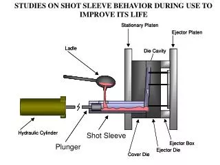
STUDIES ON SHOT SLEEVE BEHAVIOR DURING USE TO IMPROVE ITS LIFE. Stationary Platen. Ejector Platen. Ladle. Die Cavity. Hydraulic Cylinder. Shot Sleeve. Ejector Box. Plunger. Ejector Die. Cover Die. Stationary Platen. Ejector Platen. Ladle. Die Cavity. Hydraulic Cylinder. Shot Sleeve.

Ladle
E N D
Presentation Transcript
STUDIES ON SHOT SLEEVE BEHAVIOR DURING USE TO IMPROVE ITS LIFE Stationary Platen Ejector Platen Ladle Die Cavity Hydraulic Cylinder Shot Sleeve Ejector Box Plunger Ejector Die Cover Die Stationary Platen Ejector Platen Ladle Die Cavity Hydraulic Cylinder Shot Sleeve Ejector Box Plunger Ejector Die Cover Die
Steel Shot Sleeves – Modes of Failures Wash-out progressive loss of material because of corrosion and erosion Soldering adhesion and buildup of aluminum to the surface of the shot sleeve Deformation temperature gradients between bottom and top of the shot sleeve cause uneven thermal expansion Gross Cracking caused by thermal shock or severe jamming of the plunger tip Thermal Fatigue Cracking surface cracking caused by repeated thermal stress/strain Heat Lossrapid heat extraction can cause premature solidification
Damage Flow Soldering Wash-out Distortion Uneven friction Plunger/sleeve damage Plunger tip sticking Aluminum blow by Sleeve rupture Sleeve and Plunger Replacement
Basic Schematic of the Experimental Facilities Ladle Funnel Cylinder Launder Sleeve Furnace
Timing of Operation Cycle time 36 seconds Ladle Filling, 14 sec Ladle Arm Advancement, 7 sec Pouring, 4 sec Ladle Plunger Injection, 4 sec Arm Retracting, 11 sec Plunger Tip Retracting Ladle Lubrication Shot Sleeve/Plunger Tip
Design for Accelerated Testing of Nitrided Shot Sleeve Under pour hole area
Under pour hole area Design for Accelerated Testing of Shot Sleeves with (TiAl)N PVD Coating, Stellite #6 Insert and Thermal Sprayed Molybdenum Coating
Shot Sleeve Failure – Damaged Area Under Pouring Hole
Nitrided H13 Shot Sleeve - Temperature Measurement Under The Pouring Hole 0.060” 0.060” Shot sleeve and plunger tip were both nitrided H13 > 1000 °F
0.060” 0.060” Nitrided H13 Shot Sleeve Temperature Measurement
Schematic of the Washout/Soldering Testing Arrangement Al jet from slit ca. 70 in/sec Cavity Test Pins Plunger Shot Sleeve
Schematic Diagram of the Accelerated Test Die Gate Test pin Die cavity Molten Aluminum Plunger Shot sleeve
Test Pin, Test Pin Location and Casting Design Pin location Test pin Casting 5 Biscuit Runner Gate 10
Effect of Coating on Washout by Pin Testing H13-Base (TiAl)N PVD Multilayer Coated H13 Nitrided H13
Washout Resistance of Slected Materials by Pin Testing 100 shots 100 shots 50 shots 100 shots
Damage Evolution on Nitrided H13 Sleeve 600 shots 1000 shots 2200 shots 1600 shots
The Mechanism of Soldering and Wash-out in Nitrided H13 • Soldering initiates by intermetallic formation at aluminum-steel interface • Wash-out takes place by iron dissolution at aluminum -intermetallic interface • Both processes involve diffusion of aluminum and iron across the interfaces Nitrided Layer H13 substrate x 100 Aluminum Intermetallic H13 substrate x 200 x 50
Damage Depth of Nitrided H13 Sleeve - Longitudinal Section Through the Area Under Pouring Hole Soldered Aluminum 0.50" initial 0.33" final Steel Shot Sleeve Original ID surface Thermocouple Hole
TiAlN PVD Coating • Inert in molten aluminum • Relatively thick coating (10-12 mm) • Thermal conductivity similar with steel’s • Very high hardness/strength • Very low steel-coating friction coefficient
Welded plug Stellite 6 Welded Insert • Lower solubility in molten aluminum than Fe • Wear resistant • Thermal expansion and conductivity similar with steel’s • High hardness/strength Steel plug with Stellite 6 weldment about 6 mm Welded plug
Methods For Improving the Shot Sleeves Stellite 6 Welded Insert Note: Dimensions are in inch.
Molybdenum Thermal Sprayed Coating • Very low solubility in molten aluminum • Thicker than TiAlN PVD (~250 mm) • High thermal conductivity • Good hardness/strength • - Very good thermal fatigue properties Pouring hole Molybdenum thermal sprayed coating (250 mm)
Depth of Damage vs. Number of Cycles Nitrided H13 Stellite 6 insert TiAlN coated Molybdenum thermal spray
Area of Damage vs. Number of Cycles Nitrided H13 Stellite 6 insert TiAlN coated Molybdenum thermal spray
CONCLUSIONS • The molybdenum coating provided the very best material for avoiding damage to the shot sleeve steel. The molybdenum held up longer than any other material. With an improved bond, the molybdenum coating would have lasted for a longer period of time. • The hard coating (TiAlN PVD) performed excellent manner as long as the coating was maintained. However, its thickness was limited to about 10 microns (0.01 mm). After this coating wore off, the behavior was that of the nitrided H13. • 3. Stellite 6 material showed considerable wear under the action of the molten aluminum alloy; cracking occurred in the weldment. The wear is the result of solubility of cobalt in molten aluminum. • 4. The nitrided coating of the H13 provided some assistance to withstanding the wearing and soldering effect on the H13 shot sleeve.
Acknowledgements This research work is supported by DOE funds provided through by Casting Metals Coalition program. The NADCA and the members of Die Materials Committee in that Association approved this work and provided background. The appreciation of this group of people is hereby acknowledged.