Object Modeling
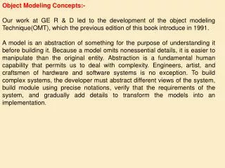
This overview presents the essential concepts of 3D object modeling, including transformations, projections, and basic geometric shapes like lines, planes, and spheres. Key transformations such as translation, scaling, rotation, and their representations using matrices are discussed in detail. The chapter introduces the notion of homogeneous coordinates and outlines how transformations are applied in hierarchical modeling. Additionally, it differentiates between parallel and perspective projections, highlighting their impact on visual representation in graphics. This foundational knowledge is essential for creating computer graphics at a basic and advanced level.

Object Modeling
E N D
Presentation Transcript
Overview • Introduction • Object transformations • Lines • Planes • Spheres • Polygonal objects • Hierarchical modeling • OpenGL details
Introduction • One step in the creation of a computer graphic image is the definition of the objects in the scene • The shape of simple objects such as planes and spheres will be discussed in this chapter • More complex curved surfaces will be discussed in the next chapter
Transformations • Transformations are needed to: • Position objects defined relative to the origin • Build scenes based on hierarchies • Project objects from three to two dimensions • Transformations include: • Translation • Scaling • Rotation • Projections • Transformations can be represented by matrices and matrix multiplication
Homogeneous Coordinates • The three dimensional point (x, y, z) is represented by the homogeneous coordinate (x, y, z, 1) • Some transformations will alter this fourth component so it is no longer 1 • In general, the homogeneous coordinate (x, y, z, w) represents the three dimensional point (x/w, y/w, z/w)
Translations • The amount of the translation is added to or subtracted from the x, y, and z coordinates • In general, this is done with the equations: xn = x + tx yn = y + ty zn = z + tz • This can also be done with the matrix multiplication:
Scaling • Scaling increases or decreases the size of the object • Scaling occurs with respect to the origin • If the object is not centered at the origin, it will move in addition to changing size • In general, this is done with the equations: xn = sx * x yn = sy * y zn = sz * z • This can also be done with the matrix multiplication:
Scaling • Scaling can be done relative to the object center with a composite transformation • Scaling an object centered at (cx, cy, cz) is done with the matrix multiplication:
Rotation • Rotation can be done around any line or vector • Rotations are commonly specified around the x, y, or z axis • A positive angle of rotation results in a counterclockwise movement when looked at from the positive axis direction • When rotating around an axis, the coordinate from that axis will not change
Rotation • The matrix form for rotation around the x, y, and z axis are: • x axis • y axis • z axis
Order of Transformations • Matrix multiplication is not commutative so changing the order of transformation can change the result • For example, changing the order of a translation and a rotation produces a different result:
Projection • A projection transformation moves from three dimensions to two dimensions • Projections occur based on the viewpoint and the viewing direction • Projections move objects onto a projection plane • Projections are classified based on the direction of projection, the projection plane normal, the view direction, and the viewpoint • Two primary classifications are parallel and perspective
Parallel Projection • All projectors run parallel and in the viewing direction • Projecting onto the z = 0 plane along the z axis results in all z coordinates being set to zero
Parallel Projection • Parallel projection can be done with the matrix multiplication: • Parallel projections do not give visual clues as to distance (foreshortening)
Perspective Projection • The viewpoint is the center of projection for a perspective projection • With the viewpoint at the origin and the projection plane at z = d, a projector from (xO, yO, zO) intersects the plane d / zO along that line • The intersection point is (xO * d / zO, yO * d / zO, zO * d / zO)
Perspective Projection • In general, the intersection point is calculated by: xn = x * d / z yn = y * d / z zn = z * d / z = d • Homogeneous coordinates are needed to put this into matrix form:
Combining Transformations • Matrices can be multiplied together to accomplish multiple transformations with one matrix • A matrix is built with successive transformations occurring from right to left • A combination matrix is typically built from the identity matrix with each new transformation added by multiplying it on the left of the current combination
Lines • Not a significant component of scenes, but the basis for many parts of graphics • The parametric equation for a line from P0 to P1 is: L(t) = (1 – t) * P0 + t * P1 • As t takes on values from the range [0, 1], L(t) traces out the line between the two points • An alternative form for this equation is: L(t) = P0 + t * (P1 – P0) = P0 + t * v • Where v is the vector P1 – P0
Planes • A plane is defined by three points that are not co-linear • Graphics is concerned with finite patches of these infinite planes • Because the vertices of a triangular patch define the plane containing it, triangular patches are always planar • The parametric form for a triangular patch is: P(s, t) = (1 – s) * ((1 – t) * P0 + t * P1) + s * P2
Scan Converting a Triangular Patch • The parametric equation for the sides can be used to identify where each row of pixels crosses the patch • The orientation of the patch determines which edges get used for each part of the patch
Patch Rendering Problems • Patches with more than three vertices may not be planar making interpolation inaccurate • A better alternative is to break a larger patch into triangular pieces • Interpolation of a non-triangular patch can also depend on orientation
Patch Rendering Problems • A polygon is convex if a line connecting any two points inside the polygon is entirely in the polygon • Scan conversion algorithms assume convex polygons • Concave polygons can be broken down into convex pieces • Triangular patches are always convex
Spheres • Can be specified by giving the radius and the center location • Locations on the surface of the sphere are given by the equation: (x – xc)2 + (y – yc)2 + (z – zc)2 = r2 • Points on the silhouette of the sphere satisfy the equation: (x – xc)2 + (y – yc)2 = r2 • Locations within this circle can be plugged back into the sphere equation to find the z coordinate for the location • This process is very computationally expensive
Spheres • One improvement on this process uses the eight-way symmetry of a circle • Once one point on the circle has been found negating and swapping the values produces seven other values on the circle • Though this is faster, the overall process is still slow because of squaring and squareroots
Spheres • Bresenham produced an algorithm to determine locations on the perimeter of a circle with just increments and addition • This algorithm can also be used to identify the locations on the front surface of a sphere
Polygonal Objects • Objects with curved surfaces can be approximated with a collection of planar patches • These patch collections can come from: • A mathematical description of the surface • A digitized version of the real object
Polygon Meshes • Can be stored as an array of polygonal patches, but • There will be a lot of duplicated data • It is difficult to determine how patches are spatially related • Changed object properties must be propagated to all of the patches
Triangular Meshes • Data duplication can be reduced through the use of two lists, but patches still function independently • A vertex list will store each vertex and its properties once • A triangle list will give the index of the vertices for each patch
Winged-Edge Data Structure • Data structure is built on the concept of an edge • For each edge, the vertices, adjacent faces, and adjacent edges are stored
Level of Detail • How detailed should an object model be? • Level of Detail research uses human perception to answer this question • Objects that will be small in the scene or may be moving fast in an animation may need less detail (i.e., fewer larger patches)
Hierarchical Modeling • Objects are described in terms of their parts • The parts may be further defined in terms of subparts • Transformations can be applied to get subparts in the correct place and size within the part and the part in the correct place and size within the object
Hierarchical Modeling • Low-level objects can be reused in the definition of a hierarchical model
Scene Graphs • A scene graph is a type of hierarchical model • Scene graphs are used in Java 3D
Hierarchical Modeling • A stack of transformation matrices helps with hierarchical models • As the program moves down the hierarchy, the current transformation is pushed before the new transformation is added • As the program moves up the hierarchy, the top of the stack is used, which removes the transformations added lower in the hierarchy
OpenGL Coordinate Systems • OpenGL uses a right-handed coordinate system • The meaning of the coordinate values can vary by application • The range of visible coordinates is determined by calls to glOrtho and glFrustum
The Grand, Fixed Coordinate System • When transformations are given, they are applied to the local coordinate system of the object • If a sequence of transformations are envisioned to get an object into the correct position within a grand and fixed coordinate system, those transformations are specified in the reverse order in OpenGL
Transformation Matrices • OpenGL has two transformation matrices called the projection and model view matrices • Only one of those is manipulated at a time • glMatrixMode(GL_PROJECTION) • glMatrixMode(GL_MODELVIEW) • The glLoadIdentity() routine initializes the current matrix to the identity
Transformations • The glRotatef and glRotated routines take four parameters: • The angle • The (x, y, z) values of the vector to rotate around • The glTranslatef and glTranslated routines take three parameters representing the x, y, and z translation amount • The glScalef and glScaled routines take three parameters representing the x, y, and z scale amount
Matrix Stacks • OpenGL has a stack for the projection and model view matrices • The projection matrix stack can hold at least two matrices • The model view matrix stack can hold at least 32 matrices • The glPushMatrix makes a copy of the the current matrix and pushed it onto the correct stack • The glPopMatrix removes the top matrix from the stack and makes that the current matrix
Simple Objects • Object vertices and their properties are specified between calls to glBegin and glEnd • The parameter to glBegin indicates what is being specified • GL_POINTS • GL_LINES, GL_LINE_STRIP, GL_LINE_LOOP • GL_POLYGON • GL_TRIANGLE, GL_TRIANGLE_STRIP, GL_TRIANGLE_FAN • GL_QUAD, GL_QUAD_STRIP
Points • The vertices specified between the begin and end are drawn as individual points
Lines • Pairs of vertices are used to draw separate lines for GL_LINES • Lines are drawn between every pair of vertices for GL_LINE_STRIP • A line is also drawn between the first and last vertex for a GL_LINE_LOOP • Any extra vertices are ignored
Polygons • The area surrounded by the lines defined by the vertices is drawn filled in based on other OpenGL parameters
Triangles • Each set of three vertices is drawn as a triangular polygon for GL_TRIANGLES • Each extra vertex adds a new triangular patch using the previous two vertices for GL_TRIANGLE_STRIP • The first vertex is used with each other pair of vertices for GL_TRIANGLE_FAN • Any extra vertices are ignored
Quads • Each set of four vertices is drawn as a four-sided patch for GL_QUADS • Each extra pair of vertices adds a new four-sided patch using the previous two vertices for GL_QUAD_STRIP • Any extra vertices are ignored
GLUT Objects • The GLUT provides routines to draw a set of objects • glutWireSphere and glutSolidSphere • Radius, slices, stacks • glutWireCube and glutSolidCube • Size • glutWireTorus and glutSolidTorus • Inner radius, outer radius, sides, rings • glutWireCone and glutSolidCone • Base radius, height, slices, stacks
GLUT Objects • glutWireIcosahedron and glutSolidIcosahedron • glutWireDodecahedron and glutSolidDodecahedron • glutWireOctahedron and glutSolidOctahedron • glutWireTetrahedron and glutSolidTetrahedron • glutWireTeapot and glutSolidTeapot • Size