Resistor and Resistance
Resistor and Resistance. Shatin Tsung Tsin Secondary School Mr. C.K. Yu. How do electrons (charges) flow within a conductor. Direction of electron flows. Direction of current Current : flow of positive charges. How do electrons (charges) flow within a conductor.

Resistor and Resistance
E N D
Presentation Transcript
Resistor and Resistance Shatin Tsung Tsin Secondary School Mr. C.K. Yu
How do electrons (charges) flow within a conductor Direction of electron flows Direction of current Current : flow of positive charges
How do electrons (charges) flow within a conductor When electrons travel through, they bump onto the outer electrons or the atoms and energies are given to the conductor.
Ohm’s Law (i) Conductors (導電體) are material which can conduct electricity (傳電). (ii) Electrons (negative charges) or positive charges can go through conductor. (iii) Negative charges give energy to the conductor when they travel through the conductor.
Ohm’s Law (iv) If there is a potential difference across a conductor, a current will flow through the conductor. (v) Ohm discovered (發現) that, in some conductors, the current (I) and the potential difference or voltage (V) across the conductor is directly proportional.
Ohm’s Law (vi) So, his discovery is called Ohm's law. The proportional constant (the slope) is called the resistance of that material
Ohm’s Law-summary Ohm’s law states that the p.d. across an ohmic conductor is directlyproportional to the current through it, provided that the temperature and other physical conditions are constant (the same). The proportional constant is called resistance . A material is called ohmic material if it follows the ohm’s law
Experiment – Ohm’s Law Objective : To verify the ohm’s law Apparatus: 1 power supply 1 resistor (red) 1 voltmeter 1 ammeter 1 circuit board connecting wires 1 switch
Experiment – Ohm’s Law • Your power supply consists of 4 electric cells. In this experiment, you are to measure the relationship between the current passing through and the potentialdifference across a resistor.
Experiment – Ohm’s Law • Connect a red resistor, an ammeter, a switch and a power supply (4 cells) in series as shown in Figure 1. Figure 1
Experiment – Ohm’s Law 2. Close the switch and measure the current shown in the ammeter, record the reading in Table 1.
Table 1 == ========
Experiment – Ohm’s Law • Keep the switch closed. Use the voltmeter to measure the potential difference across the red resistor as shown in figure 2. Record the reading in Table 1. Figure 2
Experiment – Ohm’s Law 4. Repeat steps 1 to 3 with different numbers of electric cells in the power supply. Also record the results in Table 1.
Experiment – Ohm’s Law 5.In the graph below , plot the graph of V against I. V/V I/A
Experiment – Conclusion The proportional constant (resistance) of the resistor is : ___________ Ω Ohm’s law states that the p.d. across a conductor is __________ proportional to the current through it, provided that the ___________ and other physical conditions are constant. The ratio of p.d./current is the resistance of the conductor. It is measured in ___________. directly temperature Ohm, or Ω
HOT questions If the battery of a circuit is exhausted, what will happen to the current in the circuit? • __________________________________ What are the possible reasons if the current in a circuit increases? • ____________________________________________________________________ The current will decrease and become zero. Either the resistance is lower or the supply source is of higher emf.
Resistors (i)Any conductors which work under Ohm's Law are called resistor. (ii)The proportional constant(正比常數) of voltage and current is called the resistance (電阻值) of that conductor. (iii)Unit of resistance is "Ohm", or W .
12W Resistors (iv)The symbol of a resistor in a circuit : (v)The mathematical equation for Ohm’s law is: Where R : the resistance of the resistor, V : the voltage across the resistor, I : the current flow through the resistor. e.g.
(c) Simple resistor circuit 15 Ω The values of R, V, I follows the ohm’s law.
Example 5 C of charge passes a resistor in a circuit in 2 s, the total electrical energy dissipated by the charge is 8 J. (i) What is the resistance of the resistor ? V = E / Q = 8 J / 5C = 1.6 V I = Q / t = 5 C /2 s = 2.5 A R = V / I = 1.6 V / 2.5 A = 0.64 W
Example 5 C of charge passes a resistor in a circuit in 2 s, the total electrical energy dissipated by the charge is 8 J. (ii) What is the power dissipation of the resistor ? P = E / t = 8 J / 2 s = 4 W
Revisit of Electric Power E ( by definition) = P t = P (V=E/Q,I=Q/t, V x I=E/ t) V x I (I = V/R) = P V2 / R (V = I R) = P I2 R
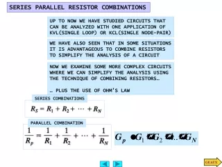
Resistors in series • Resistors can be connected together at each end. (ii) One of the basic methods is to connect the resistors one by one in a line, called in series.
RT Resistors in series (iii) The following diagram shows three resistors connected in series : (iv) they can be considered as a single resistor, with a total resistance RT. All charges flow through R1 will also flow through R2 and R3 RT follows Ohm’s law
Resistors in series In calculation : RT = R1 + R2 + R3 + ….. Example : R1 = 5 W, R2 = 3 W , R3 = 5 W If the above three resistors are connected in series, the total resistance is ______________________ 5 W + 3 W + 5 W = 13 W
A B Resistors in Parallel (i) Another method is to connect the resistors one over another at two ends, called in parallel. (ii) The diagram shows three resistors connected in parallel : Charges flowing from A to B will only go through one of the resistors in parallel.
Resistors in Parallel (iii) These resistors can be considered as a single resistor, with a total resistance RT
Resistors in Parallel RT (iii) These resistors can be considered as a single resistor, with a total resistance RT RT follows Ohm’s law
Resistors in Parallel In calculation : + … … … Example : R1 = 5 W, R2 = 10 W , R3 = 5 W If the above three resistors are connected in parallel, the total resistance is __ W . 2
Examples • Two resistors of 5 ohms and 15 ohms are connected in series. The total resistance is ______ ohms. 20
Examples • Three resistors of the same resistance are connected in series and the total resistance is 15 ohms. What is the resistance of each resistor? 5 ohms
Examples • Two resistors of the same resistance are connected in parallel and the total resistance is 5 ohms. What is the resistance of each resistor? 10 ohms
Examples • Two resistors are connected in parallel and the total resistance is 4 ohms. One of them is 5 ohms, what is the resistance of the other resistor? 20 ohms
Examples • Three resistors are connected in parallel and the total resistance is 2 ohms. Two of them are 5 ohms and 10 ohms, what is the resistance of the third resistor? 5 ohms
Class Example (i) If 2 resistors of 2 Ω and 5 Ω are connected in series, the total resistance is : R1 = 2 W, R2 = 5 W By RT = R1 + R2 = 2 + 5 = 7 Ω
Class practices (ii) If 4 resistors of 2W, 3W , 8W and 9 W, are connected in series, the total resistance is : The total resistance is : 2+3+8+9 = 22W
Class practices (iii) If 2 resistors of 2W and 5W, are connected in parallel, the total resistance is : The total resistance : 1/R = 1/2+1/5 = 7/10 R = 10/7 or 1 3/7 W
Class practices (iv) If 4 resistors of 2W, 3W, 8Wand 9W, are connected in parallel, the total resistance is : The total resistance : 1/R = 1/2+1/3+1/8+1/9 = (36+24+9+8)/72 =77/72 R = 72/77 W
Class Practices If 3 resistors of 2W, 3W, 8W are connected in series and then in parallel with a resistor of 9W, the total resistance of this connection is : The total resistance : 1/R = 1/(2+3+8)+1/9 = (9+13)/117 =22/117 R = 117/22 or 5 7/22 W
HOT – Home Practice • Only resistors of 5 ohms are given. How do we connect the resistors to form a total resistance of 4 ohms?
Summary (i) Resistors connected either in series or in parallel can be considered as a single resistor of resistance RT. (ii) The current and the voltage across the resistors or the equivalent resistor can also be calculated using the equations : RT = VT / IT
Simple measurement experiments • Objectives: • Measure current and voltage with ammeter and voltmeter • Find out the characteristics of resistors connected in parallel
Construct the circuit as shown by connecting a 6V battery and two identical resistors, R1 and R2 , in parallel. Show your connection to your teacher.
Connect an Ammeter in series with each resistor to measure current I1 and I2.(I1 and I2 can be called branch currents) I1=_______ A I2=_______ A
Then connect an ammeter in series with the battery as shown in the diagram. Measure the current I. I=_______ A Compare the three reading, I1, I2, and I I=_______ + ________ = ________ A I1 I2
Finally, connect a Voltmeter, in turns, in parallel across each resistor to measure p.d. across each of them respectively p.d. across R1 =____V, p.d. across R2 =____V. Conclusion : The p.d. across each parallel branch is __________. the same
Summary of resistors in series or in parallel Resistors in parallel : Voltages across all branches in parallel are the same. V = V1 = V2 = V3 =…. The current before and after the resistors in parallel is the sum of the currents of all branch. I = I1+I2+I3+ ….
Summary of resistors in series or in parallel Resistors in Series : Current of each resistor in a series is the same. I = I1 = I2 = I3 =…. The p.d. (voltage) across the beginning and the end of the resistors in series is the sum of the p.d. across each resistors. V = V1+V2+V3+ ….