CNG Refuelling station
CNG Refuelling station. M.T.M. S.r.l. – BRC Gas Equipment. A company located in Cherasco (Italy), is among the world leaders in the field of designing and manufacturing of components and equipment for CNG and LPG automotive engine conversion.


CNG Refuelling station
E N D
Presentation Transcript
CNG Refuelling station
M.T.M. S.r.l. – BRC Gas Equipment A company located in Cherasco (Italy), is among the world leaders in the field of designing and manufacturing of components and equipment for CNG and LPG automotive engine conversion. After a first growth phase mainly connected to the manufacturing of LPG multivalves, M.T.M. – BRC Gas Equipment has started in the 80s the production of a complete range of LPG and CNG components; in 1991 was made the first system for carburetion close loop control and, in 1996 the very first Italian LPG/CNG MPI injection system. The staff increased progressively up to the present 500 employees working in 4 different factories, under a 40.000 m2 covered area. In the 2005, M.T.M. – BRC Gas Equipment has finalized a two years merging process with the American Impco, world leader for the industrial applications of the gaseous fuels, thus creating the world biggest manufacturing concentration in the field of the alternative fuels.
CNG Refuelling station The standard layout consists of a three stages reciprocating W compressor and an hydraulic high pressure unit of compression (BOOSTER)
CNG refuelling station The compression system is inside a 20” container that is divided in to 3 separate rooms: • 1° room in which there aren’t pipes containing gas, and that contains the electrical panel (with plc), hydraulic power station (for box handling), and pneumatic panel with air compressor.
CNG refuelling station • 2° room containing compressor, booster, lubrication and cooling equipment • 3° room containing storage tanks
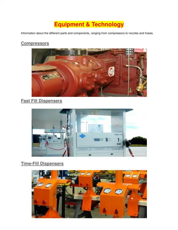
CNG refuelling station The compression station consists of the following main parts: • Connection to the feeding net with filter and safety valves (outside the compressor room) • Three stages reciprocating compressor with crankshaft, connecting rods, single effect • Medium pressure vessels for damping and storage • Booster compressor (driven by hydraulic cylinder) • High pressure vessels for damping and storage • Control panel to reduce the pressure from the high pressure storage to the dispenser • Safety valves with pneumatic actuator and filter/condensate drainage system between storage cylinders and dispenser • Dispenser • Cooling system.
CNG Refuelling station System management All control parameters can be set through PLC. Using the pressure transducers and a specific software, it is possible to guarantee an efficient scheduled maintenance.It’s alsoavailable an optional modem for the remote control of the station.
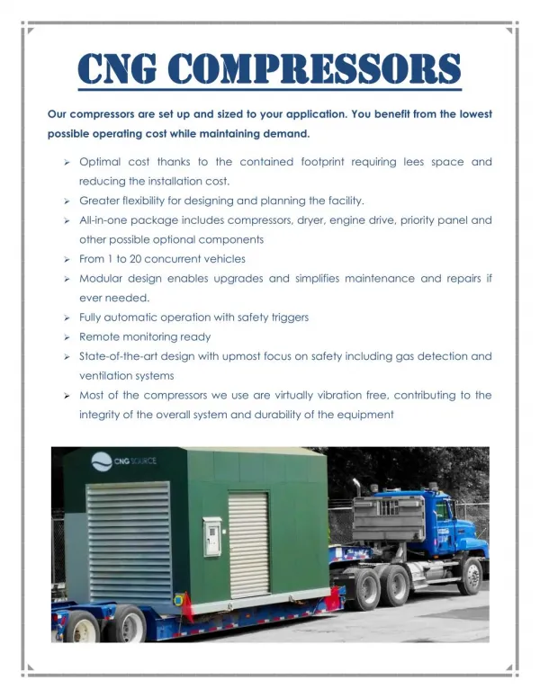
BRC Compressors BRC Compressors are specifically developed for CNG applications to obtain the maximum safety, efficiency, reliability and easy maintenance. The BRC compression systems completely designed and industrialized within our Technical departments, by the use of the most advanced instruments for safe dimensioning and design.
W Compressors The shape of BRC compressor allows a good inertial balancing, keeping small external dimensions, an easy disassembling of the components and an excellent reliability of the whole system.
W Compressors Innovative technical solutions A particular care has been used for the filtering of vapor and other impurities which can be present in the pipeline network gas. Further the oil leakage in the compressed gas has been reduced to a minimum, using specific oil wiping rings and multiple “dry” sealing systems. To enable the compressor work without lubrication, sealing and driving elements made by P.T.F.E. have been used, reinforced by other synthetic materials according to the most updated technology.
W Compressors Cooling and lubrication systems The compressors are completely cooled by a specific forced fluid flowing inside a closed circuit while the compressed gas is cooled at each stage outlet to enhance the efficiency of the machine and increase the durability of the sealing elements. The pressurized lubrication system is automatically managed by a PLC and it is independently driven by a separated electrical engine so that a proper lubrication is ensured in any working conditions.
W Compressors Lower vibration and noise levels The slow rotation speeds let us to warranty a longer durability for the components and lower vibrations and noise. Even the preferred choice to connect the electrical engine and the compressor module through a flexible joint is guaranteeing better efficiency, lower noise level, lower maintenance requirements and smaller dimensions.
W Compressors W is a reciprocating compressor with crankshaft-connecting rod-crosshead-piston rod-piston kinematic motion; it consists of three single effect cylinders, one for each compression stage. Gas suction and discharge are obtained by a concentric valve with rings and plastic seals.
BRC Compressors The above characteristics are just an indication. The capacity and power characteristics could change according CNG composition, ambient conditions and P&I configuration. The BRC compression stations can be personalized to make them suitable for the different customers’ needs. The basic three stages, single effect configuration can be modified according to the requested flows and inlet and outlet pressures.
BOOSTER Compressors BOOSTER is a reciprocating compressor driven by a hydraulic double effect, cylinder. It’s, in fact, a fourth compression stage that allows to fill the high pressure storage tanks.