Download
1 / 17
180 likes | 287 Vues
This project focuses on developing a hydraulically driven vehicle that enhances fuel efficiency by optimizing engine operation. Traditional auto engines often run at less than ideal RPMs, wasting capacity and fuel. Our design employs a water pump to create pressure, which is then stored in a pressure tank for later use. The goal is to use a small engine to maintain cruising velocity and store energy during braking. Key components include a gas-powered pump, pressure tank, and a water turbine. The prototype successfully demonstrated energy storage capabilities and offered valuable manufacturing experience.

E N D
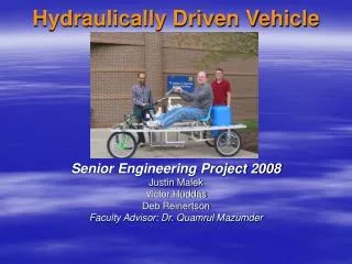
Hydraulically Driven Vehicle Senior Engineering Project 2008 Justin Malek Victor Huddas Deb Reinertson Faculty Advisor: Dr. Quamrul Mazumder
Problem • Automobile engines today are used to accelerate the vehicle to cruising velocity • After that point, the engine operates at minimal capacity. • The engine does not operate at the most fuel efficient RPM. • The engine has usage capacity that is never used.
Why Hydraulic Vehicle • Operate a small engine at an ideal speed at all times • Store excess energy • Call on stored energy when accelerating • Use engine to maintain cruising velocity • During the braking and stationary times, the engine will be storing energy for the next acceleration.
Storing Energy A water pump will be used to develop water pressure A pressure tank will store excess energy from the water pressure A water turbine will convert the stored energy into torque
Project Scope • An existing moon buggy project frame was used. • The hydraulic system was added : • Storage Tank • Gas Water Pump • Pressure Tank • Water Turbine • Piping
The Storage Tank • Storage Tank • Custom Made • Polycarbonate • Tank designed to hold 15 Gallons of Water.
Gas Pump • Gas Powered Pump • 2.5 horsepower • Capable of delivering 50 Gallons per minute • Develop Pressure around 40 PSI
Pressure Tank • Pressure Tank • 19 Gallon Capacity • Includes Air Bladder • Pressurized to 20 PSI to assist in maintaining discharge pressure.
Water Turbine • 12”x12”x5” ultra high molecular weight (UHMW) Housing • 10”x3” Impeller • 6” Diameter Core • 12 impeller blades that are 2”Lx3”W • One Nozzle Inlet and free flow outlets
Issues with Original Design • Supply tank location • Turbine Location • Turbine Design • Gas Pump Location • Pressure Tank Pre-charge
Upgraded Design • Supply tank was moved from top of the frame to bottom of the frame • Turbine was moved • Motor and Pump was rearranged • Piping rearranged to meet system requirements
Testing • Maximum distance traveled using only pressurized water • Change Precharge in tank • Maximum velocity achieved
Conclusion • Original time to complete project was greatly under estimated. • Positive displacement turbine would give better results. We could not manufacture one, and they are priced too high. • Excellent experience with manufacturing and assembly.