Aircraft Structures
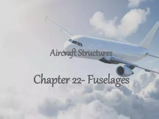
Aircraft Structures. Chapter 22- Fuselages. Fuselage Structures. Stresses in an Aircraft Fuselage. Aircraft fuselages consist of thin sheets of material stiffened by large numbers of longitudinal stringers together with transverse frames.

Aircraft Structures
E N D
Presentation Transcript
Aircraft Structures Chapter 22- Fuselages
Stresses in an Aircraft Fuselage Aircraft fuselages consist of thin sheets of material stiffened by large numbers of longitudinal stringers together with transverse frames. The distance between stringers is usually small, so that the variation in shear flow in the connection panel is small. Therefore, it is reasonable to assume that the shear flow is constant between adjacent stringers, so that the analysis simplifies to the analysis of an idealized section in which the stingers/booms carry all the direct stresses while the skin is effective only in shear.
22.1 Bending We will use this equation in this chapter to calculate the direct stress in each boom. Remember this from chapter 16! To find the broom area: Remember this from chapter 20!
Example 22.1 The fuselage of a light passenger carrying aircraft has the circular cross-section shown below. The cross-sectional area of each stringer is 100 mm2and the vertical distance given in the figure are to the mid-line of the sectional wall at the corresponding stringer position. If the fuselage is subjected to a bending moment of 200 kN.m applied in the vertical plane of symmetry, at this section, calculate the direct stress distribution.
Example 22.1 (Cont.) How to solve?
Boom Areas Example 22.1 (Cont.) How to solve? • From Symmetry: • B1 =B9 • B2 =B8 =B10 =B16 • B3 =B7 =B11 =B15 • B4 =B6 =B12 =B14 • B5 =B13 The stringers 5 and 13 lie on the neutral axis of the section and are therefore unstressed, the calculation of boom areas B5 and B13 does not then rise.
Example 22.1 (Cont.) How to solve? • Moment of Inertia (I) Ixx =2×216.6×381.02+4×216.6×352.02+4×216.6×269.52+4×216.7×145.82 =2.52×108mm4
Example 22.1 (Cont.) How to solve? • Calculate the stresses
22.2 Shear We will use this equation to find the shear flow distribution. Remember this from chapter 20! Where =0, hence:
Example 22.2 The fuselage of Example 21.1 is subjected to a vertical shear load of 100 kN applied at a distance of 150mm from the vertical axis of symmetry as shown, for the idealized section, in Fig.22.2. Calculate the distribution of shear flow in the section.
Example 22.2 (Cont.) How to solve?
Shear flow distribution Example 22.2 (Cont.) How to solve? Open section shear flow qb
Example 22.2 (Cont.) How to solve? • Taking moments about some center Remember this from chapter 17!
Example 22.2 (Cont.) How to solve? • Taking moments about some center A= Π x 381.02= 4.56 x105 mm2
Example 22.2 (Cont.) How to solve? • Finding the shear stress distribution
22.3 Torsion We will use this equation to find the shear stress distribution produce by a pure torque. Remember this from chapter 18! Lets apply it to example 22.2:
22.3 Torsion From symmetry we get:
22.4 Cut-Outs in Fuselages Loads are redistributed in the vicinity of the cut-off.
22.4 Cut-Outs in Fuselages In practice , it is necessary to provide openings in these closed stiffened shells for, for example, doors, cockpits, bomb bays and windows in passenger cabins. These openings or “cut-outs” produce discontinuities in the otherwise continuous shell structure, so that loads are redistributed in the vicinity of the cut-out, thereby affecting loads in the skin, stringers and frames.
22.4 Cut-Outs in Fuselages 3. Frequently, these regions must be heavily reinforced, resulting in unavoidable weight increases. In some cases, door openings in passenger aircraft, it is not possible to provide rigid fuselage frames on each side of the opening, because the cabin space must not be restricted. In such situations, a rigid frame is placed around the opening to resist shear loads and to transmit loads from one side of the opening to the other.
22.4 Cut-Outs in Fuselages To find the effect of cut-outs for windows:
The Trip is Over! Hope you have enjoyed it