Download
1 / 27
1.23k likes | 4.93k Vues
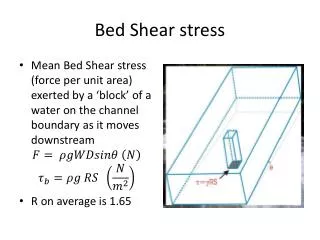
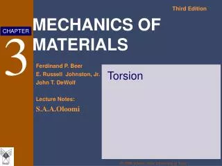
Torsion: Shear Stress & Twist (3.1-3.5). MAE 314 – Solid Mechanics Yun Jing. Torsion of Circular Shafts. In this chapter, we will examine uniaxial bars subject to torque. Where does this occur?. Transmission Shaft. Force Couples. Torsion of Circular Shafts. We assume

E N D
Torsion: Shear Stress & Twist (3.1-3.5) MAE 314 – Solid Mechanics Yun Jing Torsion: Shear Stress & Twist
Torsion of Circular Shafts • In this chapter, we will examine uniaxial bars subject to torque. • Where does this occur? Transmission Shaft Force Couples Torsion: Shear Stress & Twist
Torsion of Circular Shafts • We assume • Bar is in pure torsion • Small rotations (the length and radius will not change) • How does the bar deform? • Cross-section of the bar remains the same shape, bar is simply rotating. • Cross-section remains perpendicular to axis of cylinder (cylinder does not warp). Not true for most non-circular bars Torsion: Shear Stress & Twist
Angle of Twist • Deformation of a circular shaft subjected to pure torsion • Fix left end of shaft • A moves to A’ • = angle of twist (in radians) • What are the boundary conditions on ? • (x) = 0 at x = 0 • (x) = at x = L • For pure torsion, is linear. x Torsion: Shear Stress & Twist
Shearing Strain • Calculate the surface shear strain in thecylinder. • For pure torsion (x) = x / L, so Torsion: Shear Stress & Twist
Shearing Strain Maximum shear strain on surface • The maximum shear strain on the surface ofthe cylinder occurs when ρ=c. • We can express the shearing strain at anydistance from the axis of the shaft as Torsion: Shear Stress & Twist
Shearing Strain • We can also apply the equation for maximumsurface shear strain to a hollow circular tube. • This applies for all types of materials: elastic, linear, non-linear, plastic, etc. c c Torsion: Shear Stress & Twist
Elastic Shearing Stress • Calculate shear stress in a bar made of linearly elastic material. • Recall Hooke’s Law for shearing stress: τ=Gγ Torsion: Shear Stress & Twist
Torque • We still need to relate τ to the applied torque T, which is generally the known, applied load. • First, find the resultant moment acting on a cross-section and set this equal to T. c Torsion: Shear Stress & Twist
Torque • Continuing from previous slide: • Where J is the polar moment of inertia of the cross section of the bar (see Appendix A.3 in your textbook). • Plug this into the equation for τmax. Torsion: Shear Stress & Twist
Torque • For a non-uniform bar • For a continuously varying bar Torsion: Shear Stress & Twist
Inclined Plane • Cut a rectangular element along the plane at an angle θ. Torsion: Shear Stress & Twist
Inclined Plane x y • Sum forces in x-direction. • Sum forces in y-direction. Torsion: Shear Stress & Twist
Inclined Plane • τmax occurs at θ = 0º, ±90º • σmax occurs at θ = ±45º • τmax = σmax • When σθ is max, τθ = 0, and when τθ is max, σθ =0. Torsion: Shear Stress & Twist
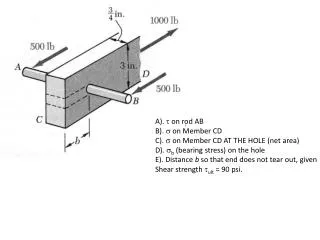
Example Problem Part 1. For the 60 mm diameter solid cylinder and loading shown, determine the maximum shearing stress. Part 2. Determine the inner diameter of the hollow cylinder , of 80 mm outer diameter, for which the maximum stress is the same as in part 1. Torsion: Shear Stress & Twist
Example Problem Part 1. For the aluminum shaft shown (G = 27 GPa), determine the torque T that causes an angle of twist of 4o. Part 2. Determine the angle of twist caused by the same torque T in a solid cylindrical shaft of the same length and cross-sectional area. Torsion: Shear Stress & Twist
Torsion: Statically Indeterminate Problems and Transmission Shafts(3.6-3.8) MAE 314 – Solid Mechanics Yun Jing Torsion: Statically Indeterminate Problems and Transmission Shafts
Statically Determinate Problems Find the maximum shearing stress in each bar. T3 T2 T1 Torsion: Statically Indeterminate Problems and Transmission Shafts
Statically Indeterminate Problems • Method for torsion is the same as the method for statically indeterminate axial load deflection problems. • Apply what you’ve already learned: • M = R – N • M = number of compatibility equations needed • R = number of unknown reactions (or internal stresses) • N = number of equilibrium equations • Compatibility equations for a torsion problem are based on angle of twist. Torsion: Statically Indeterminate Problems and Transmission Shafts
Statically Indeterminate Problems Find the largest torque T0 that can be applied to the end of shaft AB and the angle of rotation of the end A of shaft AB. Allowable shearing stress is LCD dCD dAB LAB rC rB Torsion: Statically Indeterminate Problems and Transmission Shafts
A circular shaft AB consists of a 10-in.-long, 7/8-in.-diameter steel cylinder, in which a 5-in.long,5/8-in.-diameter cavity has been drilled from end B. The shaft is attached to fixed supports at both ends, and a 90 lb.ft torque is applied at its midsection. Determine the torque exerted on the shaft by each of the supports. Torsion: Shear Stress & Twist
Transmission Shafts • In a transmission, a circular shaft transmits mechanical power from one device to another. • ω = angular speed of rotation of the shaft • The shaft applies a torque T to another device • To satisfy equilibrium the other device applies torque T to the shaft. • The power transmitted by the shaft is Generator Turbine Torsion: Statically Indeterminate Problems and Transmission Shafts
Transmission Shafts • Units for P=Tω • ω = rad/s • T = N·m (SI) • T = ft·lb (English) • P = Watts (1 W = 1 N·m/s) (SI) • P = ft·lb/s (1 horsepower = hp = 550 ft·lb/s) (English) • We can also express power in terms of frequency. Torsion: Statically Indeterminate Problems and Transmission Shafts
Example Problem A 1.5 meter long solid steel shaft of 22 mm diameter is to transmit 12 kW. Determine the minimum frequency at which the shaft can rotate, knowing that G = 77.2 GPa, that the allowable shearing stress is 30 MPa, and that the angle of twist must not exceed 3.5o. Torsion: Statically Indeterminate Problems and Transmission Shafts
Stress Concentrations in Circular Shafts • Up to now, we assumed that transmission shafts are loaded at the ends through solidly attached, rigid end plates. • In practice, torques are applied through flange couplings and fitted keyways, which produce high stress concentrations. • One way to reduce stress concentrations is through the use of a fillet. Fitted keyway Flange coupling Torsion: Statically Indeterminate Problems and Transmission Shafts
Stress Concentrations in Circular Shafts • Maximum shear stress at the fillet • Tc/J is calculated for the smaller-diameter shaft • K = stress concentration factor Fillet Torsion: Statically Indeterminate Problems and Transmission Shafts
Example Problem The stepped shaft shown rotates at 450 rpm. Knowing that r = 0.25 in, determine the maximum power that can be transmitted without exceeding an allowable shearing stress of 7500 psi. Torsion: Statically Indeterminate Problems and Transmission Shafts