DCLL TBM Design, Analysis and Development
180 likes | 193 Vues
This presentation discusses the baseline design of the DCLL (Dual Coolant Lithium Lead) breeding blanket for fusion reactors, focusing on configuration, fabrication, and design flexibility. It also explores modifications to the design to accommodate IO's goal of standardization and the possibility of a second back plate. The presentation includes a review of PbLi routing, the use of separate inlet and outlet pipes, and the potential for radial flow in the plates.

DCLL TBM Design, Analysis and Development
E N D
Presentation Transcript
DCLL TBM Design, Analysis and Development C. Wong, M. Dagher, S. Smolentsev and S. Malang FNS/TBM Meeting UCLA, September 19-20, 2007
Base-line DCLL design • Objectives: • A design that has minimum credibility issues, mainly on • configuration and fabrication, with design flexibility and • support from MHD analysis • A design should be suitable for the DEMO application • A design that is simple enough and the design team members feel comfortable with • A design approach that can aid IO’s goal of ancillary • equipment standardizationbut not given up our DCLL • design features and objectives • A design flexible enough to accommodate the look-a-like and act-a-like approachesvia the use of sub-modules
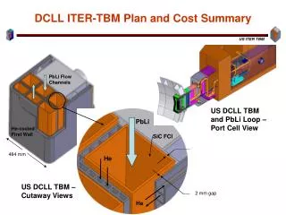
DCLL TBM Design Pb-Li Flow Channels PbLi Outlet Flow Channel PbLi Outlet Manifold PbLi Inlet Flow Channel PbLi Inlet Manifold
Helium Flow Circuit He in FW He circuit 1 TBM He circuit From Seventh Pass To Top Plate Seventh Pass FW pass 1 FW pass 2 Bottom Plate Sixth Pass From Sixth Pass From Fifth Pass Fifth Pass Fourth Pass From Fourth Pass Top Plate From Third Pass Third Pass Grid Plates Divider Plates Second Pass From Second Pass Back Plate From 1st Pass He in START: Into 1st Pass (Includes Bottom Plate) He out
Top Plate He Flow Channels Flow path: circuit 1, pass 7, channels 1-3 (of 4 total) NOTICE THE COUNTERFLOW OF THE HELIUM CIRCUITS Flow path: circuit 1, pass 7, channel 4 (of 4 total) Flow path: circuit 2, pass 7, channels 1-4 (of 4 total) He Flow Into Grid Plate I am very un-easy with this top plate design and fabrication, which will have to handle all the He coolant and properly distribute the coolant through separation and grid plates. It will be more difficult for DEMO and it could create void space.
Possible modifications for the base-line DCLL • Review PbLi routing to minimize power loss to colder Helium streams, decoupled impact from FCI • To accommodate IO standardization direction change concentric PbLi pipes to two separate inlet and outlet pipes • Review helium routing scheme to the separation and grid plates • Intention of applying second backplate to accommodate act-a-like tests and sub-modules
Item 1. PbLi routing to minimize power loss to colder Helium streams, decoupling impacts from FCI DEMO energy loss: 1st estimate by Wong: With Q’’’ input and looked at T differences between channels: Case x: Front/middle/back channels Case 1: Up down down…531 Case 2: Down up up…….319 Case 3: Up down Up…….520 Case 4: Up up down…….572 Case 5: Up down up…….285 no leakage in zone 2 Case 2 seems to have lower leakage DCLL DEMO 2nd estimate by Sergey’s modeling: In terms of heat leakage into He, the case 2: Down up up option has advantages over the Case 1: up down down scheme. TBM Ref as of April 2007 TBM Base-line Sept 2007 PbLi In and out at bottom Recommendation: To assess the following in coordination with the coordination with the FCI design 1. For TBM change the PbLi to back-up front-down configuration. 2. But to avoid counter flow at the front wall, go back-down and front up configuration. Implying re-location of the PbLi inlet outlet pipes to the top PbLi In and out at top FW He should still be moving from bottom to Top.
Item 2. We may or may not evolve our design similar to the HCLL back plate design, but with separate inlet and outlet PbLi pipes design would be easier to adjust than the concentric pipes design for IO connection standardization. With the second back plate design we can test concentric pipes in future test modules. HCLL Back plate design
Item 3: Should we consider radial flow in the radial plate, and use the separation plate as helium plenum?
We will keep the first wall helium cooling configuration and Mo and Ed will assess the possibility of radial flow to cool the radial and separation plates similar to the EU HCLL approach
Item 4: Second back plate There is room here to move the shield back to accommodate a scond back plate. First back plate 1 We could add second back plate to adjust to our specific tests for future modules.
Possibility of adding a second back plate
Possibility of adding a second back plate
Proposed Modifications for base-line DCLL TBM • PbLi flow back down front up with coordination with FCI design • Replace concentric PbLi pipes with two inlet and outlet pipes • Utilize radial flow in radial plates and use separation plate as plenum • Consider the possibility of 2nd back plate option to be implemented in the future* *The 2nd back plate mostly likely will need to be fabricated from non-ferromagnetic material, and the amount of RAFM piping should also Be checked. We need to check the possible need of reducing the PbLi Tout<420 C when the compatibility of PbLi/SS becomes important. As the design evolves, design details should include improved FCI design, minimum impacts from PbLi reversed flow and meeting of material compatibility limits with minimum amount of RAFM steel