Download

1 / 71
720 likes | 915 Vues
MICE Collaboration meeting at CERN March 28 – April 1, 2004. MICE Cooling Channel --- AFC Module progress update. Wing Lau – Oxford. A progress update: Interface scope and responsibility -- defined Interface control via a global reference system -- set up

E N D
MICE Collaboration meeting at CERN March 28 – April 1, 2004 MICE Cooling Channel --- AFC Module progress update Wing Lau– Oxford
A progress update: • Interface scope and responsibility -- defined • Interface control via a global reference system -- set up • Feasibility study of using Cryo-Coolers -- started • Detail design & engineering for module connection -- started • Cost estimate and schedule of work -- prepared • Response to Safety Review committee’s comments -- drafted • Draft Re-baseline document -- prepared • R & D issues • Window measurement and burst testsKEK Absorber cryostat and mechanical seal testsWelded window tests • Detail engineering: • Cold Mass support designCoil support tube design
Interface scope & responsibility The total supply of the AFC module falls into the following categories:
Interface scope & responsibility The total supply of the AFC module falls into the following categories:
Interface scope & responsibility The total supply of the AFC module falls into the following categories:
Interface scope & responsibility The total supply of the AFC module falls into the following categories:
NIU / IIT supply KEK supply Oxford / RAL supply
Distinguishing between a stand-alone item and an interfacing item through drawing convention Stand alone items – in black, blue & red Interface items – those marked in Pink . In the MICE project, the Pink parts will have a different drawing convention. Any changes made will be notified to all the related interface suppliers for consent.
Interface control via a global reference system-- introducing the Coat hanger technique The conventional way of assembling the different parts together is by attaching the adjoining parts to a common interface boundary. Where there are multiple interfaces, or where one part joins onto another part and another part and so forth, it would be difficult to define the order of interface. It would also accumulate errors as parts are assembles related to each other only locally and not globally. This makes the checking of interface compatibility extremely difficult.
The Coat Hanger technique (continue) The conventional way of assembling the different parts together is by attaching the adjoining parts to a common interface boundary. Where there are multiple interfaces, or where one part joins onto another part and another part and so forth, it would be difficult to define the order of interface. It would also accumulate errors as parts are assembles related to each other only locally and not globally. This makes the checking of interface compatibility extremely difficult. The way to overcome this is to avoid having to assemble parts onto each other. In this new concept, every parts will have a reference centre which coincides with one of the globally registered centres designed to position the magnet modules relatively to the beam line and then to the experimental hall. This reference centre acts like a coat hanger
The Coat Hanger technique (continue) The conventional way of assembling the different parts together is by attaching the adjoining parts to a common interface boundary. Where there are multiple interfaces, or where one part joins onto another part and another part and so forth, it would be difficult to define the order of interface. It would also accumulate errors as parts are assembles related to each other only locally and not globally. This makes the checking of interface compatibility extremely difficult. The way to overcome this is to avoid having to assemble parts onto each other. In this new concept, every parts will have a reference centre which coincides with one of the globally registered centres designed to position the magnet modules relatively to the beam line and then to the experimental hall. This reference centre acts like a coat hanger The referencing system works like a global navigation system. Through the reference centres, we can refer the position of each parts to a global coordinate. By hanging the various parts to a globally registered centre, it will automatically assemble the parts to a pre-defined position. Any interface incompatibility will be easily detected as each equipment / parts will have its unique place in the global coordinate system. No two parts should have the same coordinates. We will insist on this centre being retained on all the stand alone and interface drawings.
This is how it works on MICE: There are different levels of reference centre, designated to have a similar “level” allocation as the WB packages. The level 1 reference centre is the centre of the experimental hall; The level 2 reference centres are those along the beam line centre for the positioning of each of the modules; The level 3 reference centres are the centres of the individual modules As an example:- The Focus Coil module will have a level 3 reference centre. All the parts associated with the windows and the absorber will be referenced to this level 3 reference centre. The Focus Coil modules, the Coupling Coil, the detector modules and any equipment that are aligned to the beam centre line will be referenced to the level 2 reference centre. The beam line centres will be referenced to the level 1 reference centre etc.
These parts will have level 3 reference centre attached The level 3 reference centre on the FC module
All the AFC parts will then be hung to the level 3 reference centre at the Focus Coil
Level 3 reference centres Level 2 reference centres
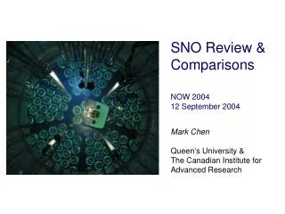
300 K Attachment Ring Cryocooler First Stage T = 25 K to T = 80 K Cryocooler Second Stage T = 2.5 K to T = 20 K The Sumitomo SDRK 415-D GM Cooler The kind of a cooler that can be used to cool MICE magnets and absorbers • From a practical standpoint the Sumitomo SDRK-415-D GM cooler (1.5 W at 4.2 K) is our the main choice to cool the MICE magnets. A pulse tube cooler from Cryomech is a distant second choice. • A two-stage cooler is needed to cool superconducting magnets. A first stage at 40 to 70 K cools the magnet shield, the cold mass support intercepts and the upper leads. The second stage (at 4 K) cools the coils and removes the heat coming down the HTS leads from the first stage. • A closed cycle cooler can not be a source of helium gas that can be used to cool gas cooled leads. Both the HTS leads and upper current leads must be conduction cooled.
Cooler Connection through a Flexible Strap The temperature drop from the load to the cold head is proportional to the strap length and inversely proportional to the strap area and the strap thermal conductivity. DT = T3 - T0 DTc = contact resistance DTc is usually small.
Cooler Connection through a Heat Pipe DTb = Boiling T Drop DTf = Condensing T Drop DTc = Contact Resistance These can be made small. DT = T3 - T0 The temperature drop from the load to the cold head is independent of the distance between the load and the cooler cold head.
Adapting a “heat pipe” arrangement for the CryoCooler in the AFC magnet cooling
Design & engineering of module connection Several connection schemes have been looked at to simplify the way the outer vessels of each modules are connected. The original thinking was to provide each connection with two “independent” joints; a flexible joint to ensure leak tightness, and a rigid connection to transmit the magnet forces from one to the other. Here are the different schemes being looked at:
Design options in the vessel connection Bellow type joint Option 2
Design options in the vessel connection Concertina type joint Option 3