Download
1 / 37
370 likes | 500 Vues
This study conducted at the William J. Hughes Technical Center examines the Future Enroute Workstation (FEWS) for Air Traffic Control (ATC) systems. Aimed to enhance traffic handling capacities by 2015, it integrates human factors principles through simulation and data collection involving programmers, controllers, and psychologists. The study evaluates variable workstation designs and their impacts on performance, workload, and situational awareness, looking to prepare ATC for anticipated increases in air traffic demand.

E N D
Future Enroute Workstation Study(FEWS) William J. Hughes Technical Center NAS Human Factors (ATO-P NAS HF) May 18 - July 27, 2005
FEWS: People • To create the simulation environment: • Programmers, • Controllers, and • Engineering Psychologists • To collect data during the simulations: • Simulation pilots, • Over-the-shoulder raters, • Simulation support staff, and • Y O U !
FEWS: People (continued) • Primary Investigator • Ben WillemsPhone: 609 485 4191 • SATCS • Randy PhillipsPhone: 609 485 4869 • Group Manager • Dr. Earl S. SteinPhone: 609 485 6389
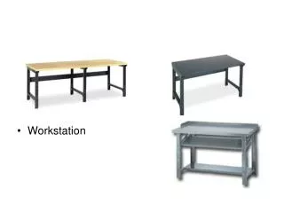
Future Enroute WorkStation • Objective: Create an en route workstation that enables controllers to handle 2015 traffic levels • Method: Systematically apply human factors principles and empirically test concept alternatives • Study designs: • Traffic Load x Workstation • (conventional) – (conventional + R-side conflict probe) • Enhanced D-side Position (At 133% Conventional) (enhanced R- and conventional D-side) – (enhanced R and D-side) • Metrics: • Performance, workload, situation awareness • Efficiency, Capacity, Safety
ATC Information and Automation • Before the early days: • Bonfires and flags • Early Days: • Abstract Airspace and Aircraft location and characteristics • The “picture” was almost completely in the controller’s head • Last 2-3 decades: • Analog and sometimes digital representation of airspace, depiction of aircraft location and features on ATC display • Separation assistance limited to short-term alert • Metering/flow advisories from flow to supervisor to sector, mostly miles in trail • Present and next decade: • More digital representation of airspace, depiction of aircraft location and features on ATC display • Separation assistance extended to medium-term conflict probe, conflict resolution assistance when needed • Passive metering assistance, metering resolution assistance when needed • Weather integration, weather reroute resolution assistance when needed
Why FEWS? • Meeting with stakeholders: • Need for a platform to use (future) automation functions • Concept Research • Human Factors Research Interests • How will controllers work with future • automation? • traffic demands? • Technology refresh necessary in en route ATC
Traffic Projections • RTCA – 150-250% increase • FAA – 25-35% increase • NASA – capacity increase
Perspectives and Recommendationson the Evolution of the En Route Sector • Roles and Responsibilities • Automation • Controller Workstation
Sector Roles and Responsibilities • Keep the sector team in tact • Modify procedures to allow controllers to take advantage of automation tools • Introduce the concept of system requests related to conflict resolution, metering, and weather. • Use NAS and NAS-wide tools to work mid– to long-term problems and maintain sector responsibilities within the 20-minute range • Use an entity (human or automation) outside of the sector to coordinate multi-sector control
Sector Roles and ResponsibilitiesKeeping the sector team in tact • Two studies showed that the D-side controller is at a disadvantage when trying to assist the R-side controller • Station keeping, e.g., separating data blocks was not that efficient • Eye movement recordings showed that the D-side controller was too often in transition • The same studies showed that D-side controllers are pulled in or confused about their role when asking to become more strategic • With introduction of automation or role change Inefficient in assisting the R-side or in using the automation
Sector Roles and ResponsibilitiesUp/Down-stream trajectory-based control • Our multi-sector study showed: • an advantage of a separate multi-sector controller • Need for different information depending on the role of the controller • But work on EDA suggests that: • controllers may be able to stay sector-based • Multi-sector or system requests can be handled in an almost tactical way
Automation • DecisionSupportSystems • Keep controllers actively involved • Indicate that assistance is available when needed • Integrate data at the interface and adapt the automation to the controller
What to automate • Human Factors suggests: Routine tasks • Other use of trajectory information • On demand highlight of aircraft at same altitude, with same destination (airport, fix) • Provide assistance when needed • Indicate that information is available and leave it to the controller to use the information when needed
WorkstationCHI Development Principles • Limit or eliminate the number of windows and lists or make them optional • Provide direct access to information in a minimum number of steps • Present information when and where needed • Prevent time sharing of information as much as possible • Keep information presentation constant between displays windows • Keep information displays of the same object connected • Keep related information close together • A constant layout assists in developing automated behaviors
Workstation • Information Display • R-side: • Show the information when and where it is needed • Support instead of replace current work practices • D-side: • Give the D-side a 2K display to accommodate need for screen real estate • Provide a situation display • Create display functions that facilitate shared situation awareness • Connect related data in a very direct way • Display Interaction • Provide an efficient way to get to and interact with the data • Use input devices consistently
WorkstationFDB Baseline (aircraft isolated) AAL123 280 T 265 123 A 450
WorkstationAdditional Information in FDBBaseline + line4 & CPDLC (aircraft isolated) AAL123 280 T 265 123 A 450 H350 S260 Interactive Fields Coordinated heading and speed no longer on flight progress strip, but in FDB instead
Automation • Current Automation • DSR emulation • User Request Evaluation Tool prototype • Traffic Management Advisor prototype • Controller Pilot Data Link Communications Build 1A • Electronic Data Panels
Automation (continued) • FEWS • Automatic Handoff Initiate • Automatic Handoff Accept • Conflict Alert • Conflict Probe • Traffic Management Advisor • Full Data Block offset • Data Entry and Display Methods • Data Link • Emphasis • Electronic Data Panels
FEWS Automation: Automatic Handoff Initiate • Similar to DSR • Change in handoff status information • Data Link equipped, • on your frequency, • aircraft handoff from your sector to sector 18 • Data Link equipped, • Not on frequency • Aircraft handoff from sector 02 to you
FEWS Automation: Emphasis • Comparable to Quick Look • Uses NAS command format and replaces the FLID with the Emphasis Key, e.g. • QZ 290 <UM>results in:
FEWS Automation: Full Data Block offset • Left click on the ACID and drag moves the FDB to any position on the display
FEWS Automation: Data Link Feedback • When a Data Link message is sent to an aircraft, the FDB provides shading of the fields to indicate that an uplink is in progress.
FEWS Automation: Data Entry and Display Methods • Display of pertinent information: • Move cursor into FDB • Second Tier of FDB displayed • Double Click on ACID • Third Tier of FDB displayed
Airspace Characteristics • Generic Airspace • Genera Center or ZGN • Based on projection of a CONUS locations onto the ZGN airspace map • E.g. flying to the North-West you will find a VOR named WAS (Washington) and to the South-East you will find a VOR named FLA (Florida) • Easy to learn • Genera is a high capacity airport • You control a high altitude feeder sector into GEN • Reduced separation standards of 3 nm and 1000 feet
Traffic Characteristics • Mostly arrival aircraft to Genera Airport • 70% of the aircraft are data link equipped • Traffic levels are 21, 28, or 35 aircraft on the frequency
OPERATIONAL • AOJ Depiction: The Area of Jurisdiction (AOJ) charts depict lateral sector boundaries as presented on the video map. • Separation: Control personnel are responsible for separation of all air traffic movements within their area of responsibility. • Altitude assignments: All aircraft shall be assigned the appropriate altitude for the direction of flight prior to entering or leaving a sector’s airspace. • Coordination for transfer of control or point out procedures shall be followed in accordance with the FAA Handbook. • Receipt of a URET flight plan, or a flight progress strip, constitutes prior coordination for inter/intra facility coordination. • DRVSM rules and altitudes apply. • 4th line data such as Speed/Headings are considered approved coordination with the next sector. • GENERA HIGH SECTOR 08 • Frequency: 120.080 • Altitude Limites: FL230 - FL600
SECTOR OPERATION • This sector serves as a transition sector for aircraft landing GEN, OHO, DETRO, KANCY & DESMN Airports in addition to the normal over-flight aircraft. • Standard Instrument Departures (SID): • GEND2, WHEEL transition • GEND2, CHIGO transition • Standard Terminal Arrival Route (STAR): • GEN1 - CHIGO transition – CHIGO PEORA GAARY ILL GEN • SGF2 – IND transition - IND DARIO OZARK SGF GEN • Sector 08 shall have control on contact for turns/descent/climb on all aircraft. • Sector 18 has control on contact for turns/descent of Genera arrivals.
TRAFFIC FLOW • Handoff GEN arrival traffic to Sector 18 at FL230 routed via GEN1 or SFG2 Star. Simultaneous arrivals are approved. • CHIGO/IND transition aircraft shall be descended prior to R22 high boundary. • As soon as practicable, handoff eastbound OHO or DETRO landing traffic to Sector 01 descending to FL220. • DESMN and KANCY arrivals shall be descended to FL220 and handed off to sector 01 prior to J13 / J23.
TRANSFER OF CONTROL • Sector 01 Frequency: 120.010 • Sector 02 Frequency: 120.020 • Sector 03 Frequency: 120.030 • Sector 07 Frequency: 120.070 • Sector 18 Frequency: 120.180 • Sector 22 Frequency: 120.220 • Sector 33 Frequency: 120.330 • Transfer of communication on all aircraft shall be accomplished prior to the sector boundary.
Thank you for joining us! Questions?
Contact Information Ben Willems FAA William J. Hughes Technical Center Building 28, ATO-P NAS-HF ACY International Airport, NJ 08405 Phone: (609) 485 4191 Fax: (609) 485 6218 E-mail: Ben.Willems@faa.gov