Download
1 / 37
370 likes | 489 Vues
Status of the LHC machine. W. Venturini Delsolaro for the LHC team IHEP 19.10.2010. OUTLINE. Nah ist Und schwer zu fassen der Gott. Wo aber Gefahr ist, wächst Das Rettende auch. Friedrich Hölderlin, 1802 Targets for 2010 and commissioning strategy Beam operation in 2010

E N D
Status of the LHC machine W. Venturini Delsolaro for the LHC team IHEP 19.10.2010
OUTLINE Nah istUnd schwer zu fassen der Gott.Wo aber Gefahr ist, wächstDas Rettende auch.Friedrich Hölderlin, 1802 • Targets for 2010 and commissioning strategy • Beam operation in 2010 • Problems encountered and how we (almost) overcame them • Overlook on 2011 and beyond
Instantaneous luminosity • Nearly all the parameters are variable (and not independent) • Number of bunches per beam kb • Number of particles per bunch • Normalized emittance n • Relativistic factor (E/m0) • Beta function at the IP * • Crossing angle factor F • Full crossing angle c • Bunch length z • Transverse beam size at the IP * • Bunch Intensity N already nominal! Total Intensity Beam Brightness • normalized emittance << nominal! Energy Interaction Region 4
Evolution of target energy When Why 7 TeV 2002-2007 Design 12 kA 5 TeV Summer 2008 Re training 9 kA SC splices Late 2008 3.5 TeV 3.5 TeV Summer 2009 Stabilizers 6 kA Fix nQPS Test 6kA 2010 1.18 TeV October 2009 nQPS 2 kA 450 GeV 5
We Run at 3.5 TeV to avoid “Silent killers” Bad surprise after gamma-ray imaging of the joints Void is present in bus extremities because SnAg flowed out during soldering of the joint
LHC Intensity limits 2010 2011 • Staged collimation system • First stage to allow 40% of nominal intensity at 7 TeV • Assumptions • LHC lifetimes and loss rates • 0.1%/s assumed (0.2h lifetime) • Ideal cleaning • Imperfections bring this down • Deformed jaws • Tilt & offset & gap errors • Machine alignment • Machine stability • Tight settings a challenge early • Intermediate settings make use of aperture to relax tolerances 0.2%/s assumed Fix Imax to 6 1013 protons per beam at 3.5TeV (about 20% nominal intensity) 30MJ stored beam energy 8
Lower energy means bigger beams Less aperture margin around the IP β* has to be increased at lower energy > 150 bunches requires crossing angle Requires more aperture Higher β* again helps Targets for 3.5 TeV 2 m no crossing angle 3 m with crossing angle β* and F in 2010-2011 9
Operation before splice consolidation Energy limited to 3.5 TeV 2010 Intensity carefully increased to collimation limit β* pushed as low as possible Target luminosity 1032 cm-2s-1 2011 Run at established limits Target integrated luminosity 1 fb-1 40% efficiency for physics → 106 seconds collisions per month 106 seconds @ <L> of 1032 cm-2 s-1→ 100 pb-1
At whatever energy Correct everything we can with safe beams Then establish references Then set up protection devices Then increase intensity incrementally Low bunch currents, increase kb Increase bunch current High bunch current, low kb, same total current Nominal bunch currents, increase kb Once kb > 50 or so, need bunch trains At each stage, re-qualify machine protection systems Commissioning strategy 11
Machine protection • MP phase 1: low intensity MP commissioning. • Commissioning of the protection systems. • Low intensity single bunch commissioning of the systems, including beam tests (manually triggered failures). • MP phase 2: MP running in with gradual intensity increase. • Intensity increase in steps, factor 2 – 4, up to ~ MJ stored energy. • Stability run of a few weeks around 1-3 MJ. • MP Phase 3: intensity increase to 10’s MJ regime. • Intensity increase in steps of 2-3 MJ (1 TEVATRON beam). • Initially planned one step every 1-2 weeks. • With the good MPS performance, agreed to reduce the step to: • 3 fills and 20 hours of stable beams to monitor and cope with the new phenomena arising when increasing the number of bunches
Good setup - hierarchy respected IP7 TCPs TCSGs TCLAs Normal cond. magnet cleaning insertion IP1 IP2 IP3 IP4 IP5 IP6 IP7 IP8 β cleaning Δp/p cleaning Dump TCTs TCTs TCTs Beam 1 The collimator hierarchy is verified with dedicated loss maps induced by artificially high loss rates: record beam losses around the ring while crossing betatron resonances. 13
fill 1418, <n> ~ 1011 , kb=248 Peak Luminosity 1032 cm-2s-1 Integrated luminosity over the fill > 2.4 (pb)^-1
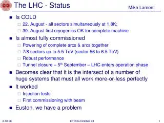
Status of the machine in short • Overall good availability (special mention for Cryogenics) • Key systems performing well, still some cleanup • Injection • Beam dumping • Collimation • Beam interlocking system (Machine Protection) • RF (power, longitudinal blow up and transverse feedback • … • Magnetically well understood and reproducible • Feedbacks on orbit and tunes operational through all cycle • Aperture is even better than expected • Small emittances, nominal bunch intensities • Excellent single beam lifetimes (vacuum, RF, optics) • Beam-beam is there but well under control (transverse FB, crossing angles)
The hump mystery Broad frequency “hump” driven beam excitation → emittance blow-up Vertical plane, worse for beam 2 Actually a fast frequency shifting oscillation with slowly drifting mean Many sources excluded, but culprit still out there 20
Ramp rate • At the start of the run the ramp rate had to be limited to 2 A/s (1.2 GeV/s) for magnet protection reasons. • Ramp duration 0.45-3.5 TeV: 46 minutes • Since mid-July the rate for down-ramps and magnet pre-cycles (magnetic history reset) was increased to nominal value of 10 A/s (6 GeV/s). • Ramp speed with beam now to 10 A/s (6 GeV/s). • Pure ramp duration 0.45-3.5 TeV: 16 minutes. 3500 GeV 2 A/s 10 A/s 450 GeV 21
Dynamic magnetic effects • Orbit, Q and Q’ decay and snapback (both on flat bottom and on flat top) • Corrections “feed forwarded” in the operational cycle B1 horizontal B1 vertical
Evidence of Beam-beam • Coherent beam-beam instabilities observed in July • Stabilized first with Octupoles and then with transverse FB
Transverse feedback Injection oscillations, dampers on Injection oscillations, dampers off
Lifetime when Reducing Crossing Angle 3 batches of 8 bunches each, spacing 150 ns up to 6 parasitic interactions per bunch 170 100 mrad 90 mrad 100 mrad 80 mrad 30 mrad 60 mrad 50 mrad 40 mrad 20 mrad 70 mrad Minimum required X-ing angle is ~100 mrad in 2010
Aperture with crossing angle on • With the 170 μrad (half) crossing angle, the on-momentum aperture in terms of nominal sigma is between 12.5 and 14.0 sigma for the two planes and two beams • Predicted 8.4 sigma in the triplet, but no aperture limit in the triplet was found with beam up to at least 13 sigma • Orbit and mechanical tolerances much better than anticipated
Some issues increasing total intensity • Tune measurement at high beam currents solved Before After change of FE
Beam driven Vacuum activity in IR Improves with time spent at same intensity and longitudinal structure. Solenoids were installed and gave indications that some of this is driven by e- cloud
FAST losses bypassing the collimation (UFO) Arc and DS BLM threshold increased by a factor 3. Seems to work with 248 bunches
Early Heavy Ion Run Parameters Initial interaction rate: 100 Hz, ~108 interaction/106s (~1 month) 33
Possible performance improvements in 2011being (carefully) considered • Run at higher N/ε? • Interesting beam physics: where is the real limit? • Increase bunch intensity • Decrease transverse emittance further • Machine protection implications to be assessed • Run at higher energy…waking up the dragon? • Risk assessment to be redone after experience with beam in 2010 • No beam induced quenches so far, better knowledge of quench limits (from tests with beam) • RRR measurements • Quench propagation measurements
2011 Q1&2 35
2011 Q3&4 36