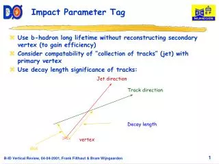
Impact parameter resolutions for ILC detector
Impact parameter resolutions for ILC detector. Tomoaki Fujikawa (Tohoku university) ACFA Workshop in Taipei Nov. 11 2004. Abstract. Study the pair e+e- background hit rate for vertex detector with various radii. (tool:CAIN,Jupiter). Optimize the vertex detector (and other detector) radii.

Impact parameter resolutions for ILC detector
E N D
Presentation Transcript
Impact parameter resolutions for ILC detector Tomoaki Fujikawa (Tohoku university) ACFA Workshop in Taipei Nov. 11 2004
Abstract Study the pair e+e- background hit rate for vertex detector with various radii. (tool:CAIN,Jupiter) Optimize the vertex detector (and other detector) radii. Obtain the impact parameter resolutions with optimized radii. (tool:TRACKERR)
Pair background hit rate study Simulation tools • CAIN (for e+e- pair background (dominant) generation) Monte-Carlo program for the beam-beam interaction. Included interactions are… ・Jupiter (for pair background hit rate estimation) JLC Uniform Particle Interaction and Tracking EmulatoR. GEANT4 based full simulator for ILC (under construction…)
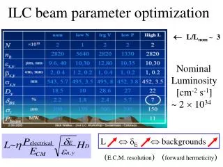
Beam parameters (input parameters for CAIN) Beam parameters are mostly same as the TESLA TDR. In order to obtain the high luminosity, beam focus is set in 250 micron in front of IP, and crab angle is included. IP = focus
Detector construction (geometry for the Jupiter) Detector is constructed with the Beam pipe, Vertex detector (Ladder construction), Intermediate tracker, Mask, etc. and base geometry is “Old” one. (Namely, designed for “Warm” machine.) The conditions for the vertex detector are as follows… These conditions are applied to estimate pair background hit rate. (charged particles are only counted)
Pair background hit rate for the vertex detector 1.hit point uniformity Hit point distribution with B = 3tesla, R1 = 1.2cm conditions. Left one shows z-phi (azimuthal angle) hit point distribution, and right one shows the z value of hit point distribution. We can use the average hit rate to estimate the background hit occupancy. (Because there are no special region which has higher hit rate.)
2.number of fired pixels Number of fired pixels per 1 track passage is about 3.7 for each detector configurations. Occupancy is assigned as 3.7 times of the total hit rate. Number of fired pixel per 1 track passage distribution.
3.radius of the vertex detector optimization fit function: (horizontal axis represents VTX detector Layer1 radii) According to this results… are desirable (if we allow 0.5% pair b.g. occupancy).
Impact parameter resolutions I estimated the impact parameter resolutions and momentum resolutions for charged pion with using optimized vertex detector (and other detector) configurations. To do so, I used a TRACKERR program. In order to compare, I estimated the impact parameter resolutions for TESLA detector too. TRACKERR: FORTRAN program to calculate tracking error matrix with using cylindrically symmetric system. Energy loss, energy loss fluctuation and multiple scattering effects are included. The main limitation is that the trajectory is not modified by energy loss.
Detector configurations for TRACKERR TESLA detector:
Impact parameter resolutions of the r-phi plane For example… Left right
Results are as follows (with Dip angle = 0): B = 5 tesla is not necessary better than 3 or 4 tesla.
Momentum resolutions For example… B4,BP500,VTX300 & TESLA B3,B4,B5, BP250, VTX300
Results are as follows (with Dip angle = 0): At high momentum region, the configuration which has low magnetic field is better than others.
New vertex detector case (which has 3 layer doublets) support VTX detector Layer
results Impact parameter resolutions (micron) At high energy region, new one has better impact parameter resolutions than that of the old one. But at the low energy region, impact parameter resolution of the new one is twice as worth as that of the old one.
Summary and Plan Summary • The configuration which has high magnetic field value does not necessary have good impact parameter resolution. • Thickness of the detector components are quite important to obtain the good impact parameters. Plan Estimate the impact parameter resolutions (and more) by using full simulator. (To do so, developments of the simulator is necessary…)