Download
1 / 37
490 likes | 1.12k Vues
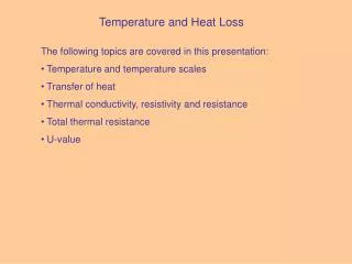
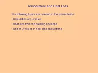
Section 7 HEAT LOSS CALCULATIONS. Objectives: - To estimate heat loss & energy consumption of a building over a period of time. Dr. Congxiao Shang. 7.0 Review: U - Values. Review – in Section 6, we learned. In thermal transmittance , the U value is simply defined as

E N D
Section 7HEAT LOSS CALCULATIONS Objectives: - To estimate heat loss & energy consumption of a building over a period of time Dr. Congxiao Shang
7.0 Review: U - Values Review – in Section 6, we learned In thermal transmittance, the U value is simply defined as 1/R; Unit: W·K-1·m-2 (Remember: R is unit area resistance, U is heat transfer per unit area) A higher R-Value means the materials are more resistant to heat loss. RUclear ? A lower U-Value means the system will transmit less heat.
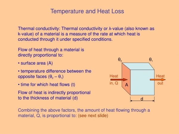
7.1 Heat Loss Rate For heat loss in a building – FIVE COMPONENT PARTS:- Losses through the walls Losses through the windows Losses through the roof Losses through the floor Losses by ventilation The value obtained is the Heat Loss Rate, W·K-1, or the heat loss per unit temperature difference, as seen from the definition of the U – value, W·K-1·m-2. Ventilation is treated differently, as seen in the next slide - This is an intrinsic factor for a particular building, it may be changed by varying the insulation of one or more components.
7.2 Ventilation For ventilation, we talk in terms of air-change rate (usually per hour) :- An air change rate of 1.0 means that the whole volume of air within a building is replaced once per hour by air from outside which then has to be heated. It is convenient to obtain a factor which is dependant on temperature difference- in terms of an equivalent U - value . The specific heat of air is about 1300 J m-3°C-1 So what is the total energy required to heat incoming air?
building volume x ( air change rate ) x temp diff. 7.2 Ventilation Divided by 3600 to bring the value to Watts (J S-1) or, building volume x ( air change rate x 0.361) x temp diff. the factor for ventilation heat loss Equivalent to U - value but the unit here is W m-3°C-1, i.e. it’s the energy “loss” per unit volume per temperature difference , whereas the U-value for the “surface” cases is, W m-2°C-1 , per unit area per temperature difference. So, what is the total heat loss rate in a building ? - see 7.3
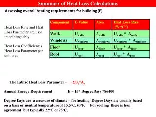
7.3 Heat Loss Calculations Hence, the total heat loss rate, H, (i.e. heat loss per temperature difference) of a room (or building) is:- H = (Area x U–Value) + Volume x ach x 0.361 Unit: W °C-1 Sum of the heat loss from “surfaces” (walls, roofs, floors, windows) the heat loss by ventilation; where “ach” is air change rate (per hour) In a steady state condition, heat loss must be replaced by heat supplied by a heating system. When you design the system, the size will depend on - the heat loss rate, H; - the internal design temperature - the external design temperature (Note: a “design” temperature is the one used as a reference for designing purposes, e.g. of heating devices)
7.3 Heat Loss Calculations Typically in the UK, the internal temperature is taken as 20 or 21 °C for residential properties, while external temperatures may vary according to external conditions - e.g. -1 °C for the UK. e.g. for a house with H = 250 W °C -1, and a design temperature difference of 20 to -1 °C (which equals 21°C) the heat loss from the house will be , 21 x 250 W = 5250 W. The heating device must be capable of supplying this amount of heat in order to maintain comfortable living conditions in this house.
7.4 Notes on sizing heating appliances For design considerations, the following points may be noted: • the design cannot assume incidental gains for sizing purposes (we then take this into account in the overall consumption). • basic heat loss calculations assume a steady state, but the actual temperature may vary below the design temperature; e.g. the designed heating system will not be able to cope with heat demand if the external temperature falls below -1°C & the internal temperature also drops. • most houses have a significant heat storage, which helps when the temperature initially falls to a low temperature. • the boiler must also be capable of supplying hot water. boiler sizes typically come in increments of 3 kW. • Hot water requirements vary with time of day, so the boiler must be able to cope with high demand (additional 3 kW). • At times of low hot water demand, this additional capacity can be used to boost the heating supply.
7.5Annual Energy Consumption for Heating We need to evaluate the overall consumption to judge the effectiveness of savings... Energy used in heating varies according to: • external temperature • incidental gains (e.g. heat from occupants, appliances, passive solar…) • dynamic considerations (e.g. timed heating, variable temperature, etc…) Detailed method:- Assess incidental gains & temperature variations throughout the year and then estimate the annual consumption. Approximate Methods:- There are various ways to adequately judge savings, e.g. the Degree-Day Method, as assumptions for each are consistent.
7.5 Annual Energy Consumption for Heating 7.5.1 Degree - Day Method – simple formula As we know, heat requirement is proportional to temperature difference. Each day when there is 1 degree of temperature difference based on the balance temperature, we add 1; when there are 2 degrees of temperature difference, we add 2 and so on. i.e. Each day when there are n degrees of temperature difference we add n Degree-Days is the sum of these numbers - East Anglia annual figure is ~ 2430 Note: the “Degree-days” assumes some incidental gains . the unit of “Degree-days” is: ºC-day
7.5 Annual Energy Consumption for Heating 7.5.1 Degree - Day Method – simple formula • There is a "free" temperature rise from the incidental gains. • The temperature at or above which no heating is required is called the neutral or balance temperature, and is normally taken as 15.5°C. This means that the effective internal temperature is taken as 15.5 °C. • If the external temperature is 14.5 °C we add 1 and so on. • However, if the temperature is greater than or equal to the neutral temperature, we add zero.
Tmax Tneutral 0.5 (Tmax+Tmin) Tmin 7.5 Annual Energy Consumption for Heating 7.5.2 Degree - Day Method – More Exact Formula In a year, there are many days when the daily temperature is partly above the neutral temperature and partly below it. The consequence is often that a small amount of heating may be required, even though the mean daily external temperature is above the neutral temperature. Considering the above, the improved method of Degree-Day: For each day, DegreeDays = Tneutral - 0.5 (Tmax +Tmin), if 0.5 (Tmax+Tmin) < Tneutral = 0,if 0.5 (Tmax+Tmin) >=Tneutral During the Heating Period: Tmax - maximum external temperature; Tmin - minimum external temperature Tneutral - neutral or base temperature.
7.5 Annual Energy Consumption for Heating 7.5.2 Degree - Day Method – More accurate Formula For each day, Tneutral If Tneutral =< Tmin, Degree-Day = 0 If Tneutral > Tmax, Degree-Day = Tneutral - 0.5 (Tmax+Tmin) If Tneutral < Tmax, then If Tneutral >=0.5 (Tmax + Tmin) Degree-Day = 0.5 (Tneutral-Tmin)- 0.25 (Tmax-Tneutral) If Tneutral <0.5 (Tmax + Tmin) Degree-Day = 0.25 (Tneutral-Tmin)
7.5 Annual Energy Consumption for Heating 7.5.2 Degree - Day Method – Note: In both methods, Degree-Days are calculated over a number of days in the period of consideration, e.g. a week, month, quarter, year. The same procedure may be used to determine the amount of energy used for cooling. In this case, there will be a cooling neutral temperature, which will normally be different from the heating one. In the UK: cooling neutral temperature= 22°C
7.5 Annual Energy Consumption for Heating 7.5.2 Degree - Day Method – for cooling Tmax Cooling Formula: Tneutral Tmin Approximately, for each day, Degree-Day = 0.5 (Tmax + Tmin)- Tneutral, if 0.5 (Tmax + Tmin) > Tneutral = 0,if 0.5 (Tmax + Tmin) =< Tneutral This formula follows the same general format as the simple heating one. There is a more accurate cooling formula similar to the more accurate heating one.
7.5 Annual Energy Consumption for Heating 7.5.3 Degree - Day Method – Degree Day Table 20-year average heating degree-days for the UK 1979 – 1998 (for reference only)
7.5 Annual Energy Consumption for Heating 7.5.4 Example using Degree-days (see also previous exam questions) Heat loss rate of a house: 450 W °C-1, and incidental gains: 2025 Watts. If there are 1100 degree-days in a 3 month period, and the thermostat is set at 20 °C, what is the balance temperature and what is the energy consumption over the period ?(Formula - see practical hand-out) Free temperature rise is 2025/450 = 4.5 °C Thus actual balance temperature = 20 - 4.5 = 15.5 °C So energy consumption over the period is (H, x Degree-day) 450 x 1100 x 86400 = 42,768,000,000 W s =~ 42.8 GJ W°C-1 °C day 1 day = 86400 seconds Note: Units
Annual Energy Consumption for Heating Energy used in heating varies according to: • external temperature • incidental gains (e.g. heat from occupants, appliances, passive solar…) • dynamic considerations (e.g. timed heating, variable temperature, etc…)
7.6 Dynamic Heating Dynamic heatingrefers to relatively detailed heating variations with temperature variations during a day (or a short period of time). For example: Variation in Boiler output with external temperature for a house. The thermostat temperature is 20°C. The climatic data refers to the period of 5th - 10th January 1985 in Norwich
7.6 Dynamic Heating Calculations are more complex in this case: Loss/gain of heat from/to a heat store during a specific time period has to be accounted for. Knowledge of the dynamic behaviour of heating is necessary . The approach taken in the lectures is a simple block model to illustrate the basic principle. In the practical a much more refined model is used which calculates changes each minute and also divides the various components. An initial assumption of the temperature profile through the walls, etc. is required (see section 6.7, page 27). The profile shown in Fig.6.7 is only true when steady state conditions exist, which in the case of a house would represent several days heating when the outside temperature was constant. In dynamic heating,the internal temperature will fall exponentially once the boiler is turned off. Alternatively if the internal temperature is constant and the boiler is kept on, the heat output from the boiler will vary if the external temperature fluctuates. Heat flows lag the change in temperature, by 6 – 9 hours in a heavy weight house ( in a brick construction); by ~ 1, in a lightweight insulated structure of timber.
7.6 Dynamic Heating 7.6.1 Response of typical house to external temperature variations in summer The internal temperature varies in a sinusoidal shape with the external temperature, but with lower amplitude and with the peaks shifted (lagged..). The heavier the construction the lower the amplitude of the internal temperature and the greater the shift. In light weight buildings - e.g. Sainsbury centre, the amplitude of the internal temperature can be quite high, though less than the external temperature.
7.6 Dynamic Heating 7.6.2 Response of a typical house to external temperature variations in winter In winter, the temperature will always be below the thermostat setting & the boiler will cut in to supply heat as required The figure shows the situation for a non-time switched case. boiler output peaks when Tex is at its lowest The output is at minimum when Tex is at a maximum • The amplitude of variation in the boiler output is again much less than the temperature. • Shaded area beneath the boiler curve represents the total energy consumed during the period.
7.6 Dynamic Heating 7.6.3 Effect of time switching – constant external temperature Boiler on periods: 07:00 - 11:00 & 17:00 - 24:00 Troom At 7am, the boiler cuts in & then T rises to the thermostat level, 20oC, shortly before it cuts out in the late morning. At 17:00, a similar thing happens. But after about 4 hours, the boiler throttles back as the thermostat level is reached. Then, the boiler output drops with time as the heat storage of the house is replenished. If the outside temperature had been constant at 0oC, the output of the boiler would have been constant at ~5.9 kW However, at the end of the day, the boiler output is actually above the steady state level due to heat in the internal fabric still being replenished.
7.6 Dynamic Heating 7.6.3 Effect of time switching – constant external temperature -A consequence of time switching is thus to require a larger boiler in order to reach thermostat level more quickly; Troom - With a larger boiler, the saving would have been less, because the mean T will be higher and the shaded area (energy consumption) is even larger. Here, the output with time switching only leads to a saving of just over 13%; Key thing about saving with time-switching: The energy required is directly proportional to mean internal temperature, If It is higher, with a large boiler or better insulation, the saving will be proportionally less.
7.6 Dynamic Heating 7.6.3 Effect of time switching – constant external temperature On the other hand, if a boiler is too small, the temperature may never quite make thermostat level and will continue to decline with time. Clearly this is a non-viable option & the theoretical saving has no meaning here. While the above graphs illustrate the situation with "idealised" boilers, i.e. the boilers throttle back, once the thermostat temperature is reached. Real boilers have some specific situations and ways to reduce the output to save energy (See notes for examples) .
7.6 Dynamic Heating 7.6.3 Effect of time switching – constant external temperature Real boilers have some specific situations and ways to reduce the output to save energy (See notes for examples): Domestic boilers are either on or off. What is the situation with time switching ? A further complication arise from the fact that there is no single thermostat level. What will be the actual temperature profile? The actual energy supplied by the boiler will reflect the external T some hours beforehand. How do you deal with this?
Annual Energy Consumption for Heating based on: • steady state condition(designed internal and external temperature; degree- day method based on a balance temperature) • dynamic heating behaviour(e.g. timed heating, temperature varies with different time, etc…)
14.5 kW 16 kW Troom Troom 16 kW 13 kW
7.7 Dynamic Heat Loss - a worked example To properly analyse the dynamic situation required “splitting” the components of the buildings into numerous sub-components, each with its own thermal capacity. E.g., a 100 mm thick brick could be divided into layers 5mm thick, and each layer would be treated as being of uniform temperature & thermal capacity. Clearly, the thinner the layer the better, but without the aid of “finite element computer modelling”, it becomes an impossible manual task. (The practical in week 7 uses a program written by a former ENV student to analyse the situation with such fine layers. The example here is just a simple approach to illustrate the basic principle)
7.7 Dynamic Heat Loss - a worked example • Example: - Waveney terrace • a thermal capacity = 4 GJ °C-1; • a heat loss rate = 45 kW °C-1; • 700 students live there, with an average body heat output of 100 W, • i.e. there is incidental gain of 700 x 100 = 70 kW; • - Time span = 2 hours; the heating goes off at midnight, the thermostat temperature is 20°C, the external temperature is 0 °C and the maximum heat supply is 2000 kW. The heat loss from the building at midnight: (20 - 0 ) x 45 = 900 kW. The net heat loss: 900 - 70 = 830 kW. Over a period of 2 hours, the total heat loss: 830 * 2 * 3600 /1000000 = 5.98 GJ Now, we can thus estimate the drop in the temperature in the building = 5.98/4 = -1.49 °C [ the 4 is the thermal capacity of the building]
7.7 Dynamic Heat Loss - a worked example We can thus work out the temperature at the end of 2 hours to be 20 - 1.49 = 18.51°C. We can use a tabular form to calculate the net heat gain or loss with different time
7.8 Energy issues with radiator on outside wall See handouts – only for those who are interested
Window = 2.4 m2 7.9 Method to determine air-change rate The method is to measure the rise in temperature above normal by providing supplementary heating to the room (in question), then we can use basic heat loss calculationsto estimate the exchange rate we need to consider not only heat loss to the outside, but also heat lost to adjoining rooms . 0ºC 0ºC Roof A room in a single storey building is 4m x 4m in plan & 2.4m high. It has one external wall with a single glazed window 2.4 m2 in area. On a day when the external temperature is 0°C, the rest of the building is heated uniformly to 20 °C. 20ºC 20ºC External wall Internal wall 2.4 20ºC Internal wall Floor Internal wall 4 0ºC 4
Window = 2.4 m2 7.9 Method to determine air-change rate Assuming all the gaps at windows and doors were sealed and supplementary heating of 1494 W was supplied to the room. After two hours the room temperature stabilised at 25°C. The specific heat of air is 1305 J m-3°C-1. How to Estimate the intrinsic ventilation rate in air changes per hour (ACH)? 0ºC U-value data are given in Table 2. 0ºC Roof 20ºC 20ºC External wall Internal wall 2.4 20ºC 25ºC Internal wall Floor Internal wall 4 Assume radiator in the room is off. 0ºC 4
Divided by 3600 to bring the value to Watts (J S-1) building volume x ( air change rate ) x temp diff. or, building volume x ( air change rate x 0.361) x temp diff. the factor for ventilation heat loss Equivalent to U - value 7.2 Ventilation
7.9 Method to determine air-exchange rate Then by Continuity, supplementary heat – (heat losses to outside + heat losses across internal walls) = ventilation losses The solution is best in tabular form
7.9 Method to determine air- change rate So, the ventilation loss = 1494-1320 = 174 W volume of room is 4 x 4 x 2.4 = 38.4 m3, and temperature difference = 25oC So, ventilation loss = 38.4 x 25 x 1305 / 3600 x ach = 174 seconds in an hour So, number of air changes per hour = 0.500