Download
1 / 36
370 likes | 484 Vues
Cementing Best Practices in Haynesville, Eagleford , and Marcellus Shale Trends. Heath Williams and Roger Keese, SPE, Schlumberger

E N D
Cementing Best Practices in Haynesville, Eagleford, and Marcellus Shale Trends Heath Williams and Roger Keese, SPE, Schlumberger Based on Papers SPE147330 presented at SPE Annual Technical Conference and Exhibition, 30 October – 2 November, 2011 and CSUG/SPE149440 presented at Canadian Unconventional Resources Conference, 15 – 17 November, 2011.
Agenda for Presentation • Brief Overview of U.S. Shale Market • Challenges with Cementing Horizontal Shale Intervals • Uncertainty about hole geometry below build section • Different operator perspectives on casing centralization • Drilling fluid properties require “fit-for-purpose” surfactant package • Cement stability hard to maintain at elevated temperature • Longterm isolation challenges • Interzonal communication • Sustained Casing Pressure (SCP) • Best Practices for Cementing Horizontal Shale Intervals • Overview of Haynesville practices and field results • Overview of Marcellus practices and field results • Conclusions and Q&A
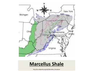
Haynesville and Marcellus Shale Technically Recoverable Shale Gas in U.S. – EIA, 2011 • 750 tcf in lower 48 US States • 75 tcf from Haynesville • 410 tcf from Marcellus
Challenges faced in Haynesville, Eagleford, and Marcellus Challenge not typically present Insufficient data collected Challenge
Operators practicing centralization and rotation in Haynesville shale Centralization in Haynesville Challenge not typically present Challenge
Effect of Rotation and Pump Rate on Narrow-Side Annular Velocity 10 bbl/min 8 bbl/min Narrow Side Velocity (ft/min 6 bbl/min 4 bbl/min 2 bbl/min Rotation speed (rpm)
Limited Carrying Capacity of Polymeric Cement Additives • Temperatures up to 400 oF • Pressures up to 12,000 psi • Relatively deep, compared with other shale plays
Sustained casing pressure (SCP) • Results • Invasion into aquifer • SCP • Atmospheric release Tensile Cracking • Potential Causes • Poor cement placement • Initial completions • Hydraulic stimulation Water Aquifer
Zonal Isolation Challenges with ConventionalCement in Horizontal Shales Mechanical property analysis with conventional system Key results • Simulation ramped up to 6,000 psi wellbore pressure • Passed compression requirements • Failed tension requirements. • Passed microannulus requirements
Typical Well Diagram/Centralizer Placement Program • Top of Centralization typically around 6,000 ft • Solid-Body Rigid Centralizers • 1 per 4 joints to Top of Lead • 1 per joint in build section • 1 per 2 joints along horizontal interval • Centralization is still less than 50% • Other strategies (casing rotation) are needed
GO/NO GO Test used in Cement Design Successful Go/No Test Result – No change in BC
Dynamic Settling Test • Highlights of Procedure • Load slurry in HPHT consistometer cup with modified paddle • Use ramp-up schedule based on well conditions – Dwell at BHCT for 30 min • Reduce motor speed down to 25 rpm for 30 min at BHCT • Cool-down and remove at 190 oF while maintaining in inverted position • Measure slurry density at top, middle, and bottom of cell • Cut cone axially along center axis • Measure height of cone at center, mid-point, ends – record maximum and average height • Acceptance criteria – < 1 ppg difference in density and 0.5 in. max. cone height.
Dynamic Stability Criteria Based on Cone Height Cone height>>0.5 in –severe sedimentation with AMPs based copolymer Cone height~0.5 in –First improvement – results not perfect. Cone height<0.5 in –System passes and is validated for field placement. Typical Dynamic Stability Test Result with Haynesville cement system above 300 degF Typical Dynamic Stability Test Result with Polymers above 300 degF
False DST Result – Sometimes a cone could indicate gelation and NOT sedimentation Under-dispersed Optimal dispersion
Pressure Matching Analysis after Haynesville Production Jobs After new approach New cementing approach introduced in Q3 2009 • 400+ jobs since introduction • 398+ successfully placed • 2 operational failures – not PSDE-related • Less scatter in WHP-pressure matching data since introduction Before new approach Pressure Match Differential (psi) Haynesville Production Cement Jobs
Typical Marcellus well program Challenges to cementing horizontal reach wells • Drilling fluid selection • Synthetic based mud used in horizontal interval • Borehole geometry • Centralization • Mud removal • Cement slurry design • Rheology • Thickening time • Fluid loss and static gel strength • Mechanical properties
Marcellus cementing approach tailored to address environmental challenges… • Flexible, expanding cement system (FECS) • High solids content • Targets multiple casing strings and multiple formations • Key properties • High solids/low permeability • Mixed continuously or batch-mixed • Acceptable static gel and compressive strength development • Low Young’s modulus • To resist fracturing and completion-induced stresses • Expansion • To close off microannuli
FECS – Testing and design • Static gel strength (SGS) development • ~30 min transition time meets API Standard 65-2 Transition time<45 min
Maximum fracturing pressure (MWP) before failure Marcellus tensile failure does not occur below 6600 psi MWP Conventional tensile failure occurs below 3000 psi MWP
Compressive and tensile failure envelopes Conventional fails in tension FECS passes CS/YM Failure Curve Tensile Strength Failure Zone Compression Failure Zone
Young’s Modulus vs. Compressive Strength Favorable YM/CS Mechanical Property Envelope for Optimal Wellbore Integrity
Marcellus cement properties • Mechanical property testing results summary
FECS – Placement evaluation Top of cement • Good cement bonding noticed after placement
Monitoring of SCP after stimulation • Stimulation maximum working pressure (MWP) • 9,000 psi MWP • Marcellus well performance after well stimulation with FECS • 40+ strings stimulated since introduction of FECS in 2011 • No SCP observed
Conclusions and Way Forward for Haynesville, Eagleford, and Marcellus Shales • Haynesville and Eaglefordshales - More stable, non-polymeric cementing approach introduced • More stability than AMPs-based polymer-stabilized systems • Very stable at 300+ degF in dynamic stability testing • Marcellus shale • Predicted conventional failure limit ~ 3,000 psi • No SCP with FECS-cemented wells stimulated at ~9,000 psi • Well stimulation in 30+ wells with FECS • No SCP observed after 6+ months • Haynesville and Marcellus shale strategies being introduced into other shale plays