Download
1 / 1
10 likes | 163 Vues
Engineering design and fabrication of x-band accelerating structure td24 with wfm. A. Solodko, A. Samoshkin , D. Gudkov, JINR, Dubna , Russia, G. Riddone, A. Andersson, Geneva, Switzerland, F. Peauger, P. Girardot, CEA Saclay, France, R . Zennaro, PSI, Villigen, Switzerland. Abstract

E N D
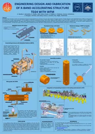
Engineering design and fabrication of x-band accelerating structure td24 with wfm A. Solodko, A. Samoshkin, D. Gudkov, JINR, Dubna, Russia, G. Riddone, A. Andersson, Geneva, Switzerland, F. Peauger, P. Girardot, CEA Saclay, France, R. Zennaro, PSI, Villigen, Switzerland Abstract To achieve high luminosity in CLIC, the accelerating structures must be aligned to an accuracy of 5 µm [1] with respect to the beam trajectory. Position detectors called Wakefield Monitors (WFM) are integrated to the structure for a beam based alignment. For the adaption of WFM the accelerating structure TD24 12GHz, based on CERN design, is used. The WFM is integrated to the structure, without modifying its accelerating and damping properties. This paper reports engineering design of a prototype accelerating structure with WFM. Precise machining of disks with a tolerance of ±2.5 µm and a surface roughness of 25 nm is demonstrated. The fabrication status of three complete accelerating structures with WFM is finally presented for a feasibility demonstration with beam in CTF3 at CERN. Wakefield monitor RF design Mechanical design of RF disks Mechanical design of WFM waveguide • 26 cells with damping waveguides • 2 couplers • 4 special regions for monitoring wakefields TOP WAVEGUIDE BOTTOM WAVEGUIDE MIDDLE CELL SiC LOAD • Cell iris shape accuracy 0.005 mm • Cell waveguide shape accuracy 0.01 mm • Flatness accuracy 0.001 mm • Cell shape roughness Ra 0.025 μm HOLES FOR PINS • Waveguide shape accuracy 0.01 mm • Waveguide shape roughness Ra 0.1 μm TE LIKE MODE SPECIAL CELL TM LIKE MODE Accelerating structure with Wakefield Monitors (WFM) HOLES FOR BOLTS The design of presented AS is based on the Tapered Damped (TD)[2,3] type cell geometry. The high-precision copper disks are joint by means of diffusion bonding, forming the body of accelerating structure. The structure is equipped with four bent waveguide connected to the middle cell. Two RF pick-ups for both horizontal and transverse modes detection are implemented on the each waveguide. REGULAR CELL COOLING TUBE WFM WAVEGUIDE STRAP Assembly procedure • Pre-assembly of couplers • Diffusion bonding of high power couplers under H2 • Re-machining of flat surface for the WR90 waveguide connection • Drilling special holes in the external butt • Assembly • Diffusion bonding of high precision disk stack and prepared couplers under H2 • Vacuum brazing of tuning studs • Fixation of WFM waveguides • Clamping of cooling blocks and cooling tubes • Tuning system • Push-pull principle • 4 tuning studs inside each cell • It is possible to increase or decrease the internal volume of each cell by deforming the thin wall. Waveguide with WFM SPECIAL CELLS THREADED ROD ACCELERATING STRUCTURE CONNECTION PLATE COOLING BLOCK FLAT SURFACE FOR WR90 WAVEGUIDE CONNECTION PUSH-PULL PUSH-PULL HOLE FOR INTEGRATION AS IN TEST ENVIROMENT PUSH-PULL PUSH-PULL Integration of Accelerating structure to the testing environment in CTF3 CONNECTER [4] The positioning of WG with WFM relative to AS is realized by two pins. A good electrical contact, needed between the WG and AS, is provided by tightening of four bolts, used for fixing the WG on the AS body. One SiC absorber, needed for damping of high-order modes, is fixed in each WG by means of bracket. The coaxial connectors with screwed RF-pick-ups are fixed directly to the adapter. ADAPTER BRACKET WFM WAVEGUIDE SiC LOAD TM LIKE MODE RF PICK-UP COUPLER COUPLER TE LIKE MODE RF PICK-UP OUTPUT WAVEGUIDES BRAZING GROOVE FEEDTROUGH [5] REGULAR CELLS REGULAR CELLS ACCELERATING STRUCTURES WITH WFM MIDDLE CELL VACUUM CONNECTION The two accelerating structure with WFM will be finally installed for a feasibility demonstration in CTF3 (CLIC Test Facility 3) at CERN. The mechanical design of the structure has taken into account the dedicated surfaces for providing integration to the testing environment. INPUT WAVEGUIDES CONCLUSION REFERENCES ACKNOWLEDGMENT [1] The CLIC Study Team, “CLIC 2008 Parameters”, CLIC-Note-764. [2] M. Dehler, I. Wilson, W. Wuensch, “A Tapered Damped Accelerating Structure for CLIC”, LINAC’98, Chicago, August 1998 [3] A. Grudiev, W. Wuensch “Design of an X-band accelerating structure for the CLIC main linac”, THP062, LINAC08, Victoria, BC, Canada. [4] http://www.meggittsafety.com [5] http://www.elhyte.fr [6] F. Peauger, W. Farabolini, P. Girardot, A. Andersson, G. Riddone, A. Samoshkin, A. Solodko, R. Zennaro, R. Ruber, “Wakefield monitor development for CLIC accelerating structure”, LINAC’10 The development described in this paper is the result of the international collaboration. The authors wish to thank all of the members of the collaboration for their valuable contribution. A new wakefield monitor design has been presented. It is integrated to the CLIC main linac accelerating structure without any major change. The wakefield monitor allows to study two kinds of hybrid HEM modes at the same time. The mechanical design has taken into account the required high gradient fabrication technologies of normal conductive cavities as well as the integration constraints in the CTF3 environment. The disks are currently in fabrication at the French company Mecachrome. The manufacturing should be finished by the end of 2010 so that low level RF tests and installation in the vacuum tank will occur in spring 2011. In parallel, the electronic acquisition system under development at CERN will be installed and first tests with beam and high power RF from PETS will be performed in 2011/2012. TUNING STUDS