Download
1 / 22
270 likes | 1.3k Vues
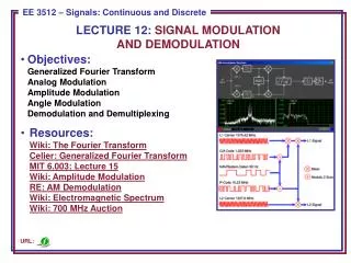
Lecture 7 AM and FM Signal Demodulation. Introduction Demodulation of AM signals Demodulation of FM Signals Regeneration of Digital Signals and Bias Distortion Noise and Transmission Line Capacity Channel capacity Conclusion. Introduction. The goal of demodulation.

E N D
Lecture 7 AM and FM Signal Demodulation • Introduction • Demodulation of AM signals • Demodulation of FM Signals • Regeneration of Digital Signals and Bias Distortion • Noise and Transmission Line Capacity • Channel capacity • Conclusion
Introduction • The goal of demodulation. • Demodulation • Regenerationcan exactly reproduce the original digital signal. • An AM signal preserves the frequency domain information of the baseband signal in each sideband, • Two methods for demodulation of an AM signal: • Envelope detection (for DSBTC AM signal) • Synchronous detection (coherent or homodyne)
FM signal demodulation • It is more resistant to noise than an AM signal. • filtering and Limiting the transmitted signal. • Differentiation to obtain the phase information in the modulated signal. • There are four ways to implement differentiation: ·Phase-Locked Loop ·Zero-Crossing Detection · FM-to-AM Conversion · Phase-Shift or Quadrature Detection
In the limit as | g | , the voltage, otherwise eout = -g or
Demodulation of FM Signal 1 - filter the signal in order to eliminate all noise outside of the signal band. Broadcast FM signals are filtered by a band-pass filter prior to transmitting. 2 - Modulated FM signal is to pass it through a limiter. This will restrict the signal amplitude to the range -VL to +VL . The output is a series of nearly rectangular pulses. 3 - low-pass filter eliminates the higher frequency components from these pulses to obtain a signal which very closely resembles the transmitted FM signal:
gfilter : gain of low-pass filter (ratio of R2 to R1 ) This amplitude variation in the received signal does not appear at the output of the low-pass filter, but the phase function (t) is preserved. After the added noise is removed, the demodulator must restore the original signal Sm (t). It is possible to accomplish this by differentiating the filtered output signal with respect to time: (Af : amplitude of filter output, Af · gfilter · VL)
By passing the differentiated signal through an ideal envelope detector and low-pass filter, we can recover the original signal. The carrier frequency determines the DC offset of this signal, which will be much larger than the varying portion of the signal: • The DC offset can be removed with a capacitor placed in series to the differentiator. The varying portion of the signal is proportional to the original signal: • There are four ways to implement a differentiator: • A.Phase-Locked Loop (PLL) • B. Zero-Crossing Detection • C. FM-to-AM Conversion (also called a slope detector) • Phase Shift or Quadrature Detection
Phase-Locked Loop (PLL) - negative feedback. The PLL consists of three basic components:A.Phase detector (PD)B. Low-pass filter (LPF)C. Voltage controlled oscillator (VCO)
Demodulation by Zero Crossing Detection • Zero crossing detector • Positive voltage. • Negative voltage. • Pulse generator. • low-pass filter. • The advantage of zero crossing detection (and FM-to-AM conversion) is that no source of the carrier frequency is required to demodulate the signal. A digital signal can easily be recovered from a FM signal in this manner. • Decoding an analog signal may be difficult by this method, since the signal at the low-pass filter output does not closely resemble the baseband signal.
Regeneration of Digital Signals and Bias Distortion • To produce rectangular pulses, we send the demodulated signal to a regenerator, which detects whether the signal level is above a certain threshold. • A poorly adjusted regenerator threshold can cause “bias distortion”, where the digital signal produced is not identical to the original signal.
Noise is any signal that interferes with a transmitted signal. It can be another message signal, a random fluctuation in the amount of signal attenuation, environmental noise, or additional voltages introduced by the transmitting or receiving equipment. N = k · T · W k: the Boltzmann constant = 1.3710 10-23 Joules per degree Kelvin T: temperature degrees Kelvin; W: bandwidth in Hertz • The channel capacity is the maximum rate at which data can be accurately transmitted over a given communication link (transmission line or radio link) under a given set of conditions. • Shannon proved that if signals are sent with power S over a transmission line perturbed by AWGN of power N, the upper limit to the channel capacity in bits per second is: • W: bandwidth of the channel in Hertz • S: power of the signal in the transmission bandwidth • N: power of the noise in the transmission bandwidth