AGATA Characterisation Group Report: Symmetric Prototype Detector Results & Future Work
220 likes | 344 Vues
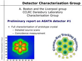
This report details the results from the AGATA Characterisation Group's scanning of the first symmetric prototype detector, including data circulation and analysis generated in both singles and coincidence modes. Comprehensive findings on radial and azimuthal response, energy gates for NaI and Ge detectors, and electric field simulations are discussed. Future plans for 2006 encompass additional coincidence scans and comparisons across facilities, with ongoing improvements to the scanning system. Access all information and data online.

AGATA Characterisation Group Report: Symmetric Prototype Detector Results & Future Work
E N D
Presentation Transcript
AGATA Characterisation Group Report • First symmetric prototype detector scanned in singles & coincidence. • Report produced and data circulated • Available from Liverpool (MTsort EG format) • Orsay (Root tree) • MGS E-field report produced • Comparison of experimental/theoretical data. • Reports produced on radial/azimuthal response. • All information is available from: • http://ns.ph.liv.ac.uk/AGATA
NaI Energy Region of Interest 288 keV 374 keV Ge Energy Experimental Set Up at Liverpool NaI AND Ge detector in coincidence to ascertain 3-D position information Ensures that only -rays scattering through an angle of 900 are recorded => accurate 3D position 11.1MBq137Cs (662keV) source scanned across front face of detector through 2mm injection collimator (70PP cps)
T90 Polar Plots Outer Contact Central Contact Core and segment energy gate 640->677keV Counts threshold >300 in the segment Core energy gate 640->677keV Counts threshold >1600 in the ring
T30 Polar Plots Outer Contact Central Contact Core and segment energy gate 640->677keV Counts threshold >300 in the segment Core energy gate 640->677keV Counts threshold >1600 in the ring
Experimental data NaI energy (keV) Ge core energy (keV) • 3 radial line-scans, 2mm spacing, 12 hours / position 30o 15o 0o • Gate on 374keV Ge and 288keV NaI energy • Gate on segment energy • Filter bad events
Problem ! ! ! E6 E5 E4 E3 E2 E1 • Gating on Ge and NaI energies, when each NaI covers multiple depths, does not work for complex segmentation
Segment pulses Centre contact pulses 6.0 mm 45.5 mm 28.5 mm 15.5 mm
I Geometry II Potential Elec field III Drift velocities IV Weighting fields AGATA symmetric crystal simulation Electric Field Simulations : MGS • Electric field simulations have been performed and details comparisons have been made with experimental pulse shape data.
Segment pulses Centre contact pulses 6.0 mm 45.5 mm 28.5 mm 15.5 mm
MGS updates since february (1) • MGS is still improving • Hole mobility model by B. Bruyneel (IKP Cologne) • Optional neutron damage simulation • New implementation of Ramo theorem (in progress) • Pulse computation • Batch mode more stable • Speed optimisation (in batch mode and GUI mode)
MGS updates since february (2) • About MGS supported platforms • Executable and source for Windows • Source for Linux: you can compile it on the Linux distribution of your choice • New web site : • MGS source and news: http://mgs2005.in2p3.fr/Mgs.php • Workshop MGS2005 site: http://mgs2005.in2p3.fr/ • Send your remarks, report the bugs to: • Mgs2005@IReS.in2p3.fr
MGS Simulation Results Z=14mm Z=8->21mm
45.5 mm 28.5 mm
Transient Magnitudes FEE in Segment 5 Z = 6mm FEE in Segment 11 Z = 15.5mm FEE in Segment 17 Z = 28.5mm
Outer Contact Risetimes – 2nd depth Beam Spot Diameter: 3.3mm Z = 15.5mm T90
AGATA Characterisation group Future Work • Plan for 2006: • Coincidence scan each of the 3 symmetric detectors. • Compare results between Liverpool, Orsay and GSI scanning system results. • Scan the first asymmetric detector. • All data to be distributed via Orsay.
Changes to Liverpool Scanning system for 2006 • Utilise 12cm long 1mm injection collimator. • First 3 z-depths 1.3mm/back 2.6mm • Unique scintillator ring for each depth • Change 11.1 MBq (70PP cps) @2mm 9cm [50/2] • 70.2MBq 137Cs (40PP cps) [20/1] or • 920MBq 137Cs (420PP cps) [200/10] • Will allow half of the detector to be scanned in coincidence. • Will perform 241Am side scan to determine segmentation boundaries.
G4 simulations have shown TOHR collimator to be too thin : double up the thickness.
GSI scanning Concept Side detector • Reduce a time to scan by taking data for all required positions at same time • Define directions of g-ray by measuring one of 511 keV g-rays from a 22Na source • Define interaction position in Ge by measuring a scattering g-ray on the side detector and energy deposit in Ge. 511g Ge Collimator (slits) 511g Collimator (holes) 22Na g source Scinti. Fiber
AGATA Characterisation group Team Meeting • Team meeting today at 5.00pm: • Laura Nelson “AGATA coincidence data analysis” • Matt Dimmock “Radial responses and effective segmentation” • Bart Burnell “12 Fold Miniball detector” • Karl Hauschild “Status of the Orsay scanning system” • Juergen Gerl “Status of the GSI scanning system”