Femtosecond Laser-Induced Periodic Surface Structures on ZnO Thin Films: Characterization and Applications
20 likes | 119 Vues
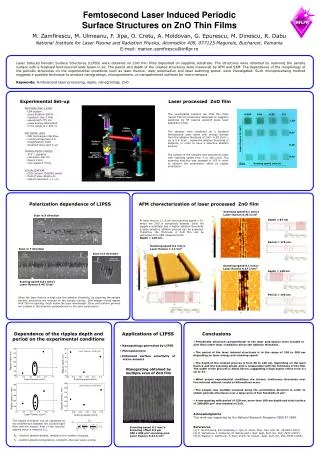
This study investigates the creation of laser-induced periodic surface structures (LIPSS) on ZnO thin films deposited on sapphire substrates using a focused femtosecond laser beam. The depth and period of the structures were analyzed using AFM and SEM, with variations in laser fluence, polarization, and scanning speed shown to significantly influence morphology. This microfabrication technique holds potential for producing nanogratings and micropolarizers, with applications in micro-sensors. Results reveal a high aspect ratio of grooves and the ability to generate continuous structures across larger areas.

Femtosecond Laser-Induced Periodic Surface Structures on ZnO Thin Films: Characterization and Applications
E N D
Presentation Transcript
INFLPR 0.005 0.01 0.05 0.1 1.10 Video camera 0.57 Laser fluence (J/cm2) Dichroic mirror 0.28 LASER beam 775 nm, 200 fs Microscope objective 100X, NA 0.5 0.45 Sample Scaning speed (mm/s) 30 µm XYZ - translation stages Femtosecond Laser Induced Periodic Surface Structures on ZnO Thin Films Laser Induced Periodic Surface Structures (LIPSS) were obtained on ZnO thin films deposited on sapphire substrate. The structures were obtained by scanning the sample surface with a focalised femtosecond laser beam in air. The period and depth of the created structures were measured by AFM and SEM. The dependence of the morphology of the periodic structures on the experimental conditions such as laser fluence, laser polarisation and laser scanning speed, were investigated. Such microprocessing method suggests a possible technique to produce nanogratings, micropolarizers, or nanopatterned surfaces for micro-sensors. M. Zamfirescu, M. Ulmeanu, F. Jipa, O. Cretu, A. Moldovan, G. Epurescu, M. Dinescu, R. DabuNational Institute for Laser Plasma and Radiation Physics, Atomistilor 409, 077125 Magurele, Bucharest, RomaniaE-mail: marian.zamfirescu@inflpr.ro Keywords: femtosecond laser processing, ripple, nanogratings, ZnO Experimental Set-up Laser processed ZnO film FEMTOSECOND LASER - CPA system - pulse duration 200 fs - repetition rate 2 KHz - wavelength 775 nm - pulse energy attenuated in the range of 1-200 nJ The investigated samples are ZnO thin films (about 150 nm thickness) deposited on sapphire substrate by RF plasma assisted pulse laser deposition (PLD). The samples were irradiated by a focalized femtosecond laser beam with energy density from the ablation threshold of ZnO - 0.28 J/cm2 , up to 0.6 J/cm2 , below the ablation threshold of sapphire, in order to have a selective ablation process. The surface of the samples was scanned by laser with scanning speed from 5 to 100 µm/s. The scanning direction was changed in XYZ in order to observe the polarization effect on ripples orientation. FOCUSING LENS - NIR microscope objective - numerical aperture 0.5 - magnification 100X - focalized laser spot 3 mm TRANSLATION STAGES - XYZ – steppers - resolution 100 nm - travel 4 mm - max speed 2 mm/s VISUALIZATION - CCD camera 752x582 pixels - field of view 40x60 mm - optical resolution < 1 mm Polarization dependence of LIPSS AFM characterization of laser processed ZnO film Scanning speed 0.1 mm/s Laser fluence 0.45 J/cm2 Scan in X direction Depth = 83 nm At laser fluence 1.1 J/cm2 and scanning speed ≤ 0.1 mm/s the ZnO is completely ablated. Since the sapphire substrate has a higher ablation threshold, a quite selective ablation process can be expected. Therefore, the thickness of ZnO film can be estimated from AFM measurements: Depth = 140 nm. 1 mm Period = 176 nm Scanning speed 0.1 mm/s Laser fluence 1.1 J/cm2 Scan in Y direction Scan in Z direction 1 mm 500 nm Scanning speed 0.1 mm/s Laser fluence 0.57 J/cm2 Depth = 140 nm Scaning speed 0.01 mm/s Laser fluence 0.45 J/cm2 Period = 190 nm When the laser fluence is kept near the ablation threshold, by scanning the sample periodic structures are induced on the sample surface. SEM images reveal ripples with 150 nm spacing, much below the laser wavelength. Clear and uniform grooves are created in the direction perpendicular to the laser polarization. Dependence of the ripples depth and period on the experimental conditions Applications of LIPSS Conclusions • Periodically structures perpendicular to the laser polarization were created in ZnO films under laser irradiation above the ablation threshold. • Nanogratings generated by LIPSS • Micropolarizers • The period of the laser induced structures is in the range of 130 to 200 nm depending on laser energy and scanning speed. • Enhanced surface sensitivity of micro-sensors • The depth of the created grooves is from 50 to 140 nm, depending on the laser fluence and the scanning speed, and is comparable with the thickness of the film. The width of the grooves is about 50 nm, suggesting a high aspect ration from 1:1 up to 3:1. Nanograting obtained by multiple scan of ZnO film • When proper experimental conditions are chosen, continuous structures over few microns without cracks or bifurcations occur. • The sample was multiple scanned along the polarization direction in order to obtain periodic structures over a large area of few hundreds of µm2. • A nanograting with period of 150 nm, more than 100 nm depth and total surface of 200x500 µm2 was created on ZnO. Acknowledgments This work was supported by the National Research Programe CEEX-ET 5848. The ripples formation can be explained as the interference between the incident light field and the electric field of the electron plasma wave in material [1]. References [1] Y. Shimotsuma, P.G. Kazansky, L. Qiu, K. Hirao, Phys. Rev. Lett. 91, 247405 (2003). [2] O. Varlamova, F. Costache, M. Ratzke and J. Reif, Appl. Surf. Sci. 253, 7932 (2007). [3] R. Wagner, J. Gottmann, A. Horn and E. W. Kreutz , Appl. Surf. Sci. 252, 8576 (2006). Scanning speed 0.1 mm/s Scanning offset 0.5 µm 200 x 500 µm2 scanning area Laser fluence 0.34 J/cm2 Ne - electron plasma density, related to the number of pulses. Te – electron plasma temperature, related to the laser pulse energy.