Download
1 / 51
710 likes | 1.23k Vues
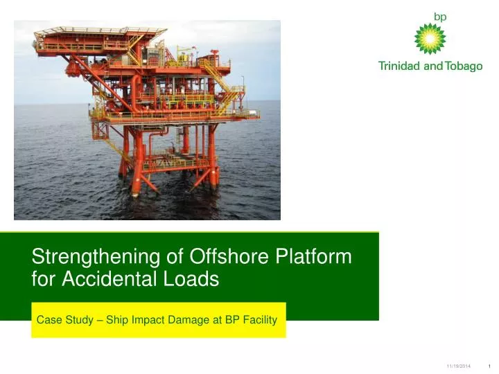
Strengthening of Offshore Platform for Accidental Loads. Case Study – Ship Impact Damage at BP Facility. Offshore Structural Engineering. Platform Description. Location – Off East Coast of Trinidad Water Depth – 278ft Helideck elevation above MSL - 91ft

E N D
Strengthening of Offshore Platform for Accidental Loads Case Study – Ship Impact Damage at BP Facility
Platform Description • Location – Off East Coast of Trinidad • Water Depth – 278ft • Helideck elevation above MSL - 91ft • Structure – X-H Braced 4 Legged jacket with skirt piles
Platform Description • Location – Off East Coast of Trinidad • Water Depth – 278ft • Helideck elevation above MSL - 91ft • Structure – X-H Braced 4 Legged jacket with skirt piles
The Incident • During a routine visit to the platform, a work crew observed items thrown about the office, as well as the platform crane dislodged from its rest position • Further investigation by the crew revealed damage to one of the platform legs at the elevation of the splash zone • At the time the structure was not yet commissioned
Damage Inspection – Topside [Leg Size: 48”f x 1”; Brace Size:24”f x 0.75”]
Damage Inspection - Topside Dented Brace Dented Leg
Engineering Evaluation Vessel Collision Damage • Structural damage was limited to Leg B1 and an adjacent brace on face elevation B
Engineering Evaluation • Dent dimension on brace = 1 ¼” deep x 12” wide • Dent depth on leg = 11”, • Leg bulge = 51 ¾” • Leg damage range from El:+15 to El: -14ft
Engineering Evaluation • Initial screening of the dent section profile at damaged area was executed using linear static analyses • The design load cases, included operational, storm and extreme level earthquake (ELE) cases • Stress utilisation at the detended section was found to well under 80%, for all inplace cases
Engineering Evaluation Preliminary analytical assessment results suggested that the structure was fit for purpose, it was however considered prudent to conduct repair work to: • Contain dent deformation under load, so that fatigue cracking would be inhibited • Reinstate resistance to possible future vessel impacts, and • Provide confidence to platform personnel that platform integrity had not been compromised
Repair / Assessment Scope Repair Dent • Appraise alternative concepts • Verify that selected repair scheme meets design basis requirements via nonlinear FE analysis • Develop design drawings of repair • Develop an installation procedure for the repair solution Global assessment of platform: • Nonlinear Pushover assessment for storm conditions • Nonlinear timehistory of platform for abnormal level earthquake conditions
Leg Repair – Concept Selection A local repair (one that does not require a change in load paths) to the leg was opted for. Three alternative concepts were considered • Weld on doubler plates/shells • Internal leg grouting • Provision of a clamp/sleeve
Leg Repair – Option 1 (Doubler Plates) • Consist of shell plates covering the dent. • a cofferdam would need to be constructed and assembled around the leg, with its lower end below the extent of the damaged region • The presence of the riser that is piggy-backed to the leg complicates the construction of the cofferdam as well as creating challenges for installation and sealing • Timescales for habitat construction would be comparatively long • The welded option was therefore discounted early on in the scheme selection process
Leg Repair – Option 2 (Grout Filled Leg) • Consist of a fully or partially grout filled leg • The basis of enhanced capacity for dented members is stabilisation of the dented cross-section • The grout does not, however, remove the eccentricity of axial load with respect to the centroid. • Practical challenges include setting of grout plug, quantity of grout required, access holes for inflatable plugs and their subsequent making good • The additional mass of grout would need consideration in seismic analyses. Also due to leg diameter heat of hydration and thermal cracking. • Internal grouting would not give platform personnel the psychological comfort of seeing a visible repair
Leg Repair Option 3 – Sleeve around Leg Clamp/sleeve technology includes four main types of strengthening/repair systems: • mechanical steel-on-steel friction clamps, • neoprene-lined clamps, • stressed grouted clamps, and • unstressed grouted clamps
Leg Repair Option 3 – Sleeve around Leg Mechanical Clamp Neoprene-lined Clamp Grouted Clamp
Clamp Detailed Design To facilitate detailed design of the clamp the following analyses were to be completed • A nonlinear FE analysis of the dent and the repaired leg so as to achieve the following • Validate the proposed design in lieu of appropriate design provisions • Determine stresses developed in the steel and grout to confirm adequacy of the flanges and grout strength • Ship impact analysis of the platform • Measured observations of the damaged leg were not able to record the bow in the leg resulting from the ship impact. The objective of this analysis was to approximate the leg bow via analytical assessment • The results were used to verify the adequacy design repair clamp-leg annulus.
Ship Impact Analysis • Preliminary estimated of energy required to produce a 11” dent on the leg was calculated as 0.72 MJ (Amdahl Equation) • Starting from impact energy of 0.72 MJ, the analyses were iterated increasing the impact energy until the observed denting deformations were reached. • This was achieved with impact energy of 2.24 MJ Post Impact Before Impact Max deformation during impact
Ship Impact Analysis • Analysis sensitivity to varying soil and dent extent investigated, was investigated • Maximum possible bow was found to be 2.4in, clamp annulus utilized was 4.5in
Finite Element Analysis Leg model with idealised dent
Finite Element Analysis Leg model with idealised dent & local buckling imperfections
Finite Element Analysis Local buckling eigenmodes
Finite Element Analysis Local deformation by local inward buckling (without sleeve clamp)
Finite Element Analysis Local deformation with sleeve clamp (local inward buckling is prevented)
Finite Element Analysis Plot of hoop stress The bolts were sized to sustain the hoop tensions on the basis of full plastic moment in the leg, and taking into account full prying action at the flanged connection
Finite Element Analysis Axial load-shortening curve for leg with & without sleeve clamp
Finite Element Analysis Moment-Curvature curve for leg with & without sleeve clamp
Finite Element Analysis Review of FE results • Friction or bond between the sleeve and the grout is not assumed. Thus, bending in the leg (from P-delta or from moment as shown by the red arrows) is resisted by bearing from the leg to the sleeve via the grout at 3 points as shown by the black arrows. • The bearing described above provides an increased inertia and thus global buckling capacity is increased.
Finite Element Analysis Review of FE results cont’d • The clamp sleeve will confine the outward radial deformation of the leg that would occur as a consequence of the leg compression • This confinement induces hoop compression in the leg and hoop tension in the sleeve • The leg is thus in biaxial compression and the clamp is in hoop tension • Local buckling is prevented in an outward radial direction by the sleeve. Also, local buckling in an inward direction is represented by non-linear geometry and large deformation in the ABAQUS model. The model (with imperfections to ensure inward local buckling) shows the failure of the un-repaired leg. This model was re-analysed with the sleeve clamp and that inward local buckling is prevented and the axial capacity is increased
Finite Element Analysis Review of FE results cont’d • Thus, internal grouting of the leg is not required – and also it would reduce the pile capacity. • The above points result in the sleeved section of the leg having a greater axial and bending capacity than the parts of the leg immediately above and below the sleeve. The capacity of the leg is thus increased to the strength (not stability) capacity of a 48”x1”x50ksi tubular. This was seen on the load shortening curves