Download
1 / 23
230 likes | 358 Vues
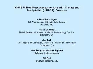
SSMIS Unified Preprocessor for Use With Climate and Precipitation (UPP-CP) Overview. Hilawe Semunegus NOAA’s National Climatic Data Center Asheville, NC Steve Swadley Naval Research Laboratory, Marine Meteorology Division Monterey, CA Joe Turk

E N D
SSMIS Unified Preprocessor for Use With Climate and Precipitation (UPP-CP) Overview Hilawe Semunegus NOAA’s National Climatic Data Center Asheville, NC Steve Swadley Naval Research Laboratory, Marine Meteorology Division Monterey, CA Joe Turk Jet Propulsion Laboratory, California Institute of Technology Pasadena, CA Wes Berg and Mathew Sapiano Colorado State University Bill Bell ECMWF, Reading, UK
Purpose • SSMIS datasets have been available since 2003, but have not yet achieved substantial usage in the climate and precipitation (CP) community • Open questions on data quality have been addressed by several user groups, most notably via the SSMIS Unified Preprocessor (UPP) jointly developed by NRL-Monterey and the UK Met Office (NWP SAF) • The analysis showed that the sensor is affected by three main phenomena, much of which cannot be accounted for by traditional inter-sensor calibrations • The goal is to adapt the UPP into a form suitable to needs of C&P community (UPP-CP), essentially to provide sensor data records (SDR) at the native SSMIS scan resolution of each channel using the modified UPP-CP software
Three Types of UPP/UPP-CP Corrections to the SSMIS TDR files • Scan Non-Uniformity Correction (all satellites) • Channel dependent multiplicative coefficient applied to each beam position from static scan non-uniformity files Reflector Emission (F16 and F17, but applied for all) • Requires knowledge of reflector temperature Trefl and frequency-dependent emissivity ε • F-16 required an emprically developed Trefl using the reflector rim temperature • F-17 - F-20 have the thermistor moved to the back of the graphite reflector shell • Radiometer Gain Correction (F16 all year, F17 at high solar elevation angles in spring and summer) • Corrects for solar intrusions into warm load resulting in short duration positive Gain anomalies • Radiometer sees warm load tines “warmer” than recorded warm load temperature, resulting in a brightness temperature depression of ~ 0.5-1.5 K • Short lived Gain anomalies are filtered using the NGST developed algorithm and available in the operationally produced gain files (one file for each TDR file)
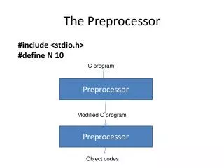
GenRemapLASBufr GenTDRdata Reads TDR file and fills each set (IMA, ENV, LAS, UAS) Native: GetSCANCoeffs Reads scan nonuniformity coefficients for sensor and channel set U A S (5) N= approx 3200 IMA (6 chans) ENV (5) LAS (8) DoScanCorrection Apply scan uniformity to IMA, ENV, LAS UPP Version 2 GetGAINdata Read gain file (N x 24 size) if provided for Gain Ratio 180 90 60 30 DOGAINCorrection Apply gain ratio to each channel set Tscene= Tcosmic + (Tobs-Tcosmic)*GR UPP: Averages all channels to LAS resolution (N/3 X 60), then calls CorrectTB to apply correction for (frequency dependent) reflector emission and spillover factor (read from external coefficient files) UPP Version 1 CalSolZenAndAz Calculate solar zenith and azimuth Add to IMA structure DetectSolarIntrusions For UPP-CP: Apply correction for reflector emission and spillover at native resolution, output data in unique binary format GenTAnt Reflector temperature extraction ProcessLASTDR_v2 Remap to LAS and apply TB corrections
Reflector Emission (~1-2K) 1) SSMIS Cal/Val team has asserted the reflector’s layered SiOx/AL VDA coating process resulted in the emissive F16 and F17 reflectors 2) Depending upon the time of year and orbital parameters (LTAN) the sensor enters Earth shadow and/or Solar Array shadowing and the reflector cools by ≈ 80K, then rapidly warms to near 300K upon exiting shadow LAS 50-60 GHz IMA 91-183 GHz ENV 19-37 GHz UAS 60 +/- GHz IMA 50-60 GHz F16: thermistor located on reflector rim, Trefl based on “lagged-derivative” approach F17-F20: thermistor moved to back to reflector, gives better estimate of Trefl F18 uses improved reflector with an order of magnitude lower reflector emissivity, F19-F20 similar If the reflector temperature Trefl and emissivity ε are known the scene temperature can be reconstructed K = spillover factor for each channel
F-16 Reflector Temperature Issue T_rflct does not keep up with the actual reflector face temperature immediately after emerging from shadow
Solar intrusions into the warm load occur 2-4 times per orbit, as evidenced by the Gain ratio, Gain_Original/Gain_Filtered F16 SSMIS Solar Intrusions (-0.5-1K) 1 June 2010 Rev 34148 Y-axis: 1-(Gain_Original/Gain_Filtered), range -0.005 to +0.005 X-axis: scanline, range 1-3200
Solar Intrusion Correction • NGST developed a correction for operational use that is applied in UPP-CP • NGST produces ancillary “gain files” which are required to apply correction • Do not know how these are produced • Currently evaluating suitability of this correction technique for climate but may be sufficient for ICDR • At this point we have more questions than answers... Example from Gain file red line: actual gain; blue line: filtered gain
SSMIS Antenna Temperature to Brightness Temperature Issues • Several corrections must be applied to SSMIS TAs to obtain TBs • Some corrections come from operational FNMOC code used to produce SDRs (TBs) from TDRs (TAs) • Solar and Lunar Intrusions (applied to F16, F17) • Corrections applied in FNMOC code based on smoothing warm/cold calibration • Applied in UPP-CP through use of “gain” files supplied by FNMOC • Emissive Antenna (applied to all, but problem worse for F16, F17) • Correction based on extrapolation of available reflected temperature and estimate of emissivity of antenna • Correction applied in UPP-CP, but not in FNMOC code • Antenna Pattern Correction (all SSMIS) • FNMOC uses spillover and cross-pol for most channels, but surface-dependent inter-calibration to SSM/I used for SSM/I channels (19, 22, 37 and 91) • Spillover and cross-polarization corrections available in FNMOC code • UPP-CP applies the spillover correction, no cross-polarization coefficients!
Current Status • The UPP is essentially a collection of Fortran90 subroutines that compile under Linux (gfortran 4.5.1/Lahey-Fortran 95/Portland Group) that read in a TDR file and its associated gain file, scan non-uniformity coefficients, reflector emissivities and spillover factors, averaging coefficient file, computes the reflector temperature, performs the calibration anomaly corrections, and outputs a BUFR and ASCII file with all 24 channels at a remapped LAS resolution • Currently have adapted various UPP subprograms to write out each channel set (IMA, ENV, LAS, UAS) at native resolution after correction for spillover and reflector emissivity (UPP-CP) • Code is being polished so that UPP-CP acts as a “filter” between the input TDR and the output “TDR”, with changes only to TB values (although after all these corrections, the output is really an SDR or brightness temperatures) • US Navy (FNMOC) plans to run an operational version after UPP-CP group solidifies antenna pattern correction coefficient issues.
CSU SSMI/SSMIS Fundamental CDR • Colorado State University (CSU) producing an FCDR of SSM/I and SSMIS under NCDC CDR program • FCDR will include QC, improved geolocation, intercalibratrion; code is open source and freely available • All three of the previously listed corrections are implemented for CSU SSMIS • Now beginning testing to understand effect on calibration of TBS produced • Will apply 4 independent intercalibration techniques (already applied to SSM/I) to check for agreement between SSMIS and SSM/I • In addition, CSU will apply new scan non-uniformity corrections and will supply inter-calibration numbers
24 March 2010 F16 Ascending 150H GHz Original TDR file Most notable changes are when the satellite is in shadow 150H GHz (TDR – UPP-CP)
1 June 2010 F16 Ascending 150H GHz Original TDR file 150H GHz (TDR – UPP)
1 October 2010 F16 Ascending 150H GHz Original TDR file 150H GHz (TDR – UPP)
Summary • SSMIS requires three major corrections • Emissive antenna: correction looks good for climate applications • Solar Intrusions: currently have some reservations about gain file technique for climate use • Not sure if current ancillary gain files correct all problems • Can be used for ICDR but cannot use gain files in CDR project – possible issues for climate, impossible to document, availability could be an issue. • Can solar intrusion correction be duplicated for transparency? • APC: do we have all the coefficients? • Currently investigating what this should be, if needed • Need to do more tests on all these corrections
24 March 2010 F16 Ascending 183±1 GHz Original TDR file 183±1 GHz (TDR – UPP)
1 June 2010 F16 Ascending 183±1 GHz Original TDR file 183±1 GHz (TDR – UPP)
1 October 2010 F16 Ascending 183±1 GHz Original TDR file 183±1 GHz (TDR – UPP)