Download
1 / 29
290 likes | 395 Vues
This study explores the production of a beam of tensor-polarized deuterons using a carbon target, based on experiments conducted at Forschungszentrum Jülich. The research delves into the optical effects related to nuclear spin dichroism and consequential calculations of polarization as a function of energy. Measurements of cross-sections and the interaction of nuclear and Coulomb forces are discussed, alongside significant experimental results that demonstrate the dependence of polarization on energy levels and target thickness. The findings advance knowledge in nuclear physics and particle interactions.

E N D
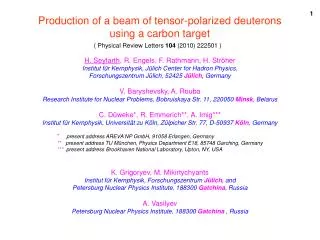
1 Production of a beam of tensor-polarized deuteronsusing a carbon target ( Physical Review Letters 104 (2010) 222501 ) H. Seyfarth, R. Engels, F. Rathmann, H. Ströher Institut für Kernphysik, Jülich Center for Hadron Physics, Forschungszentrum Jülich, 52425 Jülich, Germany V. Baryshevsky, A. Rouba Research Institute for Nuclear Problems, Bobruiskaya Str. 11, 220050 Minsk, Belarus C. Düweke*, R. Emmerich**, A. Imig*** Institut für Kernphysik, Universität zu Köln, Zülpicher Str. 77, D-50937 Köln, Germany K. Grigoryev, M. Mikirtychyants Institut für Kernphysik, Forschungszentrum Jülich, and Petersburg Nuclear Physics Institute, 188300 Gatchina, Russia A. Vasilyev Petersburg Nuclear Physics Institute, 188300 Gatchina , Russia *present address AREVA NP GmbH, 91058 Erlangen, Germany ** present address TU München, Physics Department E18, 85748 Garching, Germany *** present address Brookhaven National Laboratory, Upton, NY, USA
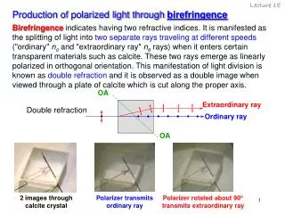
2 eo Introduction E eo Dichroism as an optical effect birefringent, uniaxial crystal like Turmalin or filter foils o optical axis I0(ρdx)=1/3∙f(σ0) σ0 Nuclear (spin) dichroism σ+1=σ-1=σ±1 m=0 initial beam: unpolarized deuterons target: spin-zero nuclei like carbon I0=1/3 I±1(ρdx)=2/3∙f(σ±1) m=+1 m=-1 I+1=1/3 ρdx I-1=1/3 I-1+I+1=I±1=2/3 I±1(ρdx) < 2I0(ρdx) → pzz(ρdx) < 0 I±1(ρdx) > 2I0(ρdx) → pzz(ρdx) > 0 I±1(ρdx) - 2I0(ρdx) def I+1(ρdx) + I-1(ρdx) - 2I0(ρdx) pzz(ρdx) = = I±1(ρdx) +I0(ρdx) I+1(ρdx) + I-1(ρdx) +I0(ρdx)
3 I±1(ρdx) - 2I0(ρdx) I±1(ρdx) , I0(ρdx) ? pzz(ρdx) = I±1(ρdx) +I0(ρdx) σ±1,0(E) E E dx σ±1,0(E(x)) E(x) Ein Eout x x=dt x=0 Tasks: calculateσ0(E), σ±1(E) and measurepzz as function of Einand dt (i.e., Eout)
4 z unpolarized deuteron beam beam direction ≡ quantization axis z m=±1 m = 0 expectation: σ0 > σ±1 resulting in pzz> 0 Relativistic energies: Calculation G. Fäldt, J. Phys. G: Nucl: Phys 6 (1980) 1513: σ0 - σ±1= + 1.87 fm2 Experiment L.S. Azhgirey et al., Particles and Nuclei, Letters 5 (2008) 728): σ0 - σ±1= + 7.18 fm2 E = 5 to 20 MeV: Calculation V. Baryshevsky and A. Rouba, Phys. Lett. B 683 (2010) 229 Optical theorem
5 V. Baryshevsky and A. Rouba, Phys. Lett. B 683 (2010) 229 NN nuclear interaction, n-C and p-C and Coulomb interaction p-C in eikonal approximation NNC interference of nuclear and Coulomb interaction in eikonal approximation cor correction term to the eikonal approximation Essential results: (a) σ0- σ±1 up to b compared to fm2=10-2 b at high energies (b) change of sign due to nuclear-Coulomb interference ρgraphite = 1 g/cm3 or 5∙1022 C atoms/cm3 Ein= 20 MeV, Eout= 11 MeV: Ein= 11 MeV, Eout= 5.5 MeV:
6 Measurements Performed with unpolarized deuteron beam from Van-de-Graaff tandem accelerator operated by Institut für Kernphysik of Universität zu Köln (J. Jolie, H. Paetz gen Schieck, J. Eberth, and A. Dewald, Nucl. Phys. News 12, 4 (2002)) target foils D1 D2 D3 Θp=24.5° incomingbeam Ein = 9.5 … 18.7 MeV Θp=0° Θp=24.5° 3 bar 3He thickness labelled mg/cm2 as empty Au 5.0 Au5 Au 9.7 Au10 C 35.90 C36 C 57.69 C58 C 93.59 C94 C 129.49 C129 C 152.63 C153 C 165.39 C165 C 187.93 C188 d + 3He → 4He + p Ecell = f(Ein, dtarget) σ(Ecell, θp)=σo(Ecell,θp)·[1+1/2·pzz(Ecell)·Azz(Ecell,θp)] known known measured to derive
D1 (2.0 ) D2 (2.5 ) D3 (3.0 ) 7 tgt Havar window 3He cell θd≤0.5 ° 132 55 64 48 cm Left (φ=0 °) 1.5 mm 24.5 ° Forward 24.5 ° Right (φ=180 °) and Up (φ=90 °), Down (φ=270 °)
9 What is expected with an unpolarized beam? σ(Ecell, θp)=σo(Ecell,θp)·[1+1/2·pzz(Ecell)·Azz(Ecell,θp)] Unpolarized cross sections from M. Bittcher et al., Few-Body Systems 9 (1990) 165 :Δ σ0(0 °) 4∙σ0(24.5 °) σ0(0 °) Δ: σ0(24.5 °) Ein (MeV) Ecell (MeV) Au5 6.20 …. 7.90 5.56 …. 7.36 C36 9.50 …. 10.50 6.06 …. 7.41 C188 17.50 …. 18.70 5.11 …. 7.78
10 p(24.5°) fnorm=0.374 p(0°)
14 Azz (Ecell, 0 °) P.A. Schmelzbach, W. Grüebler, V. König, R. Risler, D.O. Boerma, and B. Jenny, Nucl. Phys. A264, 45 (1976) . S.A. Tonsfeldt, PhD Thesis, University of North Carolina, 1983. Azz (Ecell, 24.5 °) M. Bittcher, W. Grüebler, V. König, P.A. Schmelzbach, B. Vuaridel, and J. Ulbricht, Few-Body Systems 9, 165 (1990) S.A. Tonsfeldt, PhD Thesis, University of North Carolina, 1983.
15 pzz measured at Ecell in the polarimeter cell Ecell C94 Eout Ein 6.62 MeV 7.03 MeV 13.50 MeV C129 35 94 6.63 MeV 7.04 MeV 15.40 MeV 13.50MeV pzz(Ecell) → pzz(Ein)
16 The (unexpected) experimental result pzz<0 pzz>0 ~ 14.8 MeV Theoretical values in the order of 10-2, change of sign at 11 Mev, energy dependence much slower
17 Fit by 12 Gaussian-distributed cross sections Adjustment of E0, σ(E0), Г For6 of them σ±1=0→pzz > 0 For6of themσ0=0 → pzz < 0 16.1, 16.7, and 17.5 MeV possibly caused by uncertainties in the target thicknesses σ±1 ≠ 0, σ0 = 0 → pzz < 0 σ±1 = 0, σ0≠ 0 → pzz > 0
18 σ(Eo)∙Γ(b∙MeV) 400 570 a) D. von Ehrenstein et al., Phys. Rev. Lett. 27, 107 (1971); b) P.L. Jolivette, Phys. Rev. C 9, 16 (1974); c) J. Jänecke et al., Phys. Rev. 175, 1301(1968); d) H. Vernon Smith, Jr., and H.T. Richards, Phys. Rev. Lett. 23, 1409 (1969);e) L. Meyer-Schützmeister et al.,Phys. Rev. 147, 743 (1966).
19 An attempt to interprete the two strong resonances at 14.4 and 15.4 MeV present work Eo (MeV) 14.4±0.1 15.38±0.03 σ(E0) (b) 1100±100330±40 Γ (keV) 520±100 1000±250 pzz -0.375±0.014 +0.228±0.016 E*(14N) (MeV) 22.6±0.123.44±0.03 earlier (d,α) experiments D. von Ehrenstein et al., Phys. Rev. Lett. 27, 107 (1971): E*(14N) (MeV) ~22.6~23.5 dσ/dΩ (μb/sr) ~19 ~6 P.L. Jolivette, Phys. Rev. C 9, 16 (1974): E*(14N) (MeV) 22.6±0.123.36 dσ/dΩ (μb/sr) 90 60 The giant resonance in 14N spreads around 22.5 MeV with a width (FWHM) of 3.5 MeV M. Goldhaber and E. Teller, Phys. Rev. 74, 1046 (1948): dipole vibration of the bulk of protons against that of neutrons φ=30 MeV, ε=2.4 fm, and R0=Re=3.13 fm → ћω=22.3 MeV
20 Extension of the vibrational model to 2 orthogonal vibrations in a deformed nucleus Tentative use of the quadrupole moment of the 14N ground state of +0.0193 b yields Rlong=R0+0.07 fm=3.20 fm and Rshort=R0-0.07fm=3.06 fm These modified values of R0 yield 14N*(I=1) d (I=1)12C (I=0) Rlong m=±1 Ћω (Rlong)=22.1 MeV Creation of the compound state leads to the removal of deuterons in the m=±1 state from the beam + and m=0 Ћω (Rshort)=22.6 MeV Creation of the compound state leads to the removal of deuterons in the m=0 state from the beam Rshort + The simple picture would allow a first interpretation. Is it, however, valid?
21 At present no real understanding of the surprising results, mainlydue to therequested large cross section values Extra-nuclear effects? (polarization of the deuterons in the Coulomb field, i.e., change of the deuteron wave function, spin-orbit coupling?) The results, however, would allow the (inexpensive) production of tensor-polarized deuteron beams
22 Ein at the upper edge ofthe 15.38 MeV resonance deceleration in the carbon (graphite) target with production of pzz deceleration in a sandwiched material without production of pzz Ein at the upper edge ofthe 14.4 MeV resonance
23 Confirmatory measurement under consideration: Transmission of 13.5 to 16.5 MeV deuteron beams through a 20 mg/cm2 carbon foil Energy loss in the foil ΔEd~ 1 MeV pzz= + 1, pz = 0 (100% m=±1) unpolarized beam (2/3 m=±1, 1/3 m=0) pzz= – 2, pz = 0 (100% m=0) dashed lines: with the possibly artificial resonance at 16.1 MeV Eout Ein Eout Ein Ein (MeV) Calculated with either σ0 or σ±1 equal to zero ! 13.7514.415.4MeV resonance removes m=0m=±1m=0 deuterons from the beam
24 moveable target frame or target wheel Au3 Au2 Au1 diaphragms dia2 dia3 dia1 empty detector (Faraday cup) d(Ein,Iin,pzz,pz) d(Idet) carbon1 pzz=+1, pz=0 pzz=–2, pz=0 pzzand pz≠0 (?) carbon2 shielding Idia3 Idia1 Idia2 carbon3 Idet ΣIdia
25 α emission forward L. Meyer-Schützmeister et al.,Phys. Rev. 147, 743 (1966); H. Vernon Smith, Jr., and H.T. Richards, Phys. Rev. Lett. 23, 1409 (1969); P.L. Jolivette, Phys. Rev. C 9, 16 (1974) α emission backward D. von Ehrenstein et al., Phys. Rev. Lett. 27, 107 (1971) peaks of the present fit without the possibly artificial resonances at 16.1, 16.7, and 17.5 MeV 13C(p,γ)14N F. Riess et al., Nucl. Phys. A175, 462 (1971) 14N(γ,p)13C R. Kosiek, K. Maier, and K Schlüpmann, Phys. Lett. 9, 260 (1964) Agreement in the peak positions accidental?
26 calculated measured Average values of the ratio Icup/Idiaphragamsfor the 7 carbon targets 1 Width of the angular distribution ~ dtarget→ ratio decreases with dtarget vp
27 measured fit 9.5 to 10.5 MeV fit 9.5 to 10.4 MeV calculated Energy dependence of the ratio Icup/Idiaphragamsfor the C36 carbon target Width of the angular distribution ~ (vp)-1→ ratio increases with energy
28 (L-R)/(L+R) (U-D)/(U+D)
29 (L-R)/(L+R) (U-D)/(U+D)