Calibration Talking Points
This document outlines a robust design for monitoring and calibrating various payload channels during flight operations. Key elements include real-time analysis of antenna beam patterns, pulsing systems, and gain calibrators. Methods for generating fast broadband pulses and narrow band pulses are discussed, focusing on power distribution and timing precision. The relationship between system temperature and voltage is examined to enhance calibration processes. Moreover, strategies for utilizing ground-to-balloon transmission and handling environmental impacts on system performance are analyzed, ensuring reliable data collection during missions.

Calibration Talking Points
E N D
Presentation Transcript
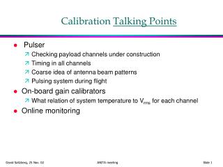
Pulser Checking payload channels under construction Timing in all channels Coarse idea of antenna beam patterns Pulsing system during flight On-board gain calibrators What relation of system temperature to Vrms for each channel Online monitoring Calibration Talking Points
Pulse types • Method 1: Fast, broadband pulse • Can get Avtech pulse ~ 200 V pk2pk into 50 • 800 W instantaneous • (eg 40 psec risetime 0.1 to 6 GHz bandwidth) • Good for timing in system (sub-nanosecond) • Power shared among bands • Method 2: • Narrow band pulse with reasonable timing: 2-10 nsec • Can amplify easily to 25 W • (up to 500 MHz, can get to ~1000 MHz?) • Gives more power in band • Not for checking triggering 40 ps r.t. Volts 1 nsec
Could reasonably transmit 25 W into 1000 MHz band Assuming 80km line of sight -80 dBm in 300 MHz thermal noise in 300 MHz bandwidth is -90 dBm So should be visible “Standard gain horn” can transmit broadband pulse with good phase center with 15 dBi directivity. Will be large for 200 MHz. But could test triggering Narrow band pulses can be more easily transmitted and detected. How many ground locations? Transmitting ground to balloon
To determine system temperature of each channel….from physics point of view, says how well we know our threshold Harsh environment could alter our gain & noise levels relative to ground Sets absolute scale of Vrms Prefer switch in load and/or noise diode in front of LNA Need to do this without reducing sensitivity of nominal system If we trust gain & noise of LNA, do this downstream of LNA? Adds complexity. Could instrument this on a few channels and carry it to others based on Vrms from ice in aperture. On board “mini-cal”
Sun: Could map out antenna beam (0.5 deg vs. ~60 deg) Intensity varies on mostly long timescales Should be bright enough to see Moon: Similar size to Sun About 200 K, but does not fill beam. Well known temperature Even using averaging SNR is very small ~10-4 Anyway get this for free with some number of random (“zero bias”) triggers (~0.1 Hz) Other in-flight calibrators
Should be monitoring data from ground Taking “zero-bias” or “minimum bias” data Vrms (Tsys) on each channel Frequency power spectrum for each channel ~1MHz res’n Trigger rates Singles rates per channel Intermediate coincidence rates Trigger rates ~ 5-10 minute time response Online Monitoring