Download
1 / 48
510 likes | 885 Vues
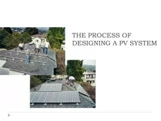
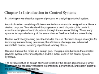
Chapter 1: Introduction to Control Systems O bjectives. In this chapter we describe a general process for designing a control system.

E N D
Chapter 1: Introduction to Control Systems Objectives In this chapter we describe a general process for designing a control system. A control system consisting of interconnected components is designed to achieve a desired purpose. To understand the purpose of a control system, it is useful to examine examples of control systems through the course of history. These early systems incorporated many of the same ideas of feedback that are in use today. Modern control engineering practice includes the use of control design strategies for improving manufacturing processes, the efficiency of energy use, advanced automobile control, including rapid transit, among others. We also discuss the notion of a design gap. The gap exists between the complex physical system under investigation and the model used in the control system synthesis. The iterative nature of design allows us to handle the design gap effectively while accomplishing necessary tradeoffs in complexity, performance, and cost in order to meet the design specifications.
Course Synopsis • Provides a background of control principles in various engineering applications. Basic mathematical tools such as Laplace transform, transfer function, block diagram, signal flow graph, mathematical modeling of dynamic systems, time response analysis, stability of linear system, root locus and frequency domain analysis are utilized.
CourseOutcomes (CO) • CO1 • Ability to apply various mathematical principles (from calculus and linear algebra) to solve control system problems. • CO2 • Ability to obtain mathematical models for such mechanical, electrical and electromechanical systems. • CO3 • Ability to derive equivalent differential equation, transfer function and state space model for a given system. • CO4 • The ability to perform system’s time and frequency-domain analysis with response to test inputs. Analysis includes the determination of the system stability.
Process – The device, plant, or system under control. The input and output relationship represents the cause-and-effect relationship of the process. System – An interconnection of elements and devices for a desired purpose. Control System – An interconnection of components forming a system configuration that will provide a desired response.
The interaction is defined in terms of variables. • System input • System output • Environmental disturbances
ControlSystem • Control is the process of causing a system variable to conform to some desired value. • ManualcontrolAutomatic control (involving machines only). • A control system is an interconnection of components forming a system configuration that will provide a desired system response. Output Signal Input Signal Control System Energy Source
Open-Loop Control Systems utilize a controller or control actuator to obtain the desired response. Closed-Loop Control Systems utilizes feedback to compare the actual output to the desired output response. Multivariable Control System
Control System Classification Missile Launcher System Open-Loop Control System
Control System Classification Missile Launcher System Closed-Loop Feedback Control System
Manual Vs Automatic Control • Control is a process of causing a system variable such as temperature or position to conform to some desired value or trajectory, called reference value or trajectory. • For example, driving a car implies controlling the vehicle to follow the desired path to arrive safely at a planned destination. • If you are driving the car yourself, you are performing manual control of the car. • If you use design a machine, or use a computer to do it, then you have built an automatic control system.
ControlSystem Classification Desired Output Response Controller Process Output Variables Multi Input Multi Output (MIMO) System Measurement
Purpose of Control Systems • Power Amplification (Gain) • Positioning of a large radar antenna by low-power rotation of a knob • Remote Control • Robotic arm used to pick up radioactive materials • Convenience of Input Form • Changing room temperature by thermostat position • Compensation for Disturbances • Controlling antenna position in the presence of large wind disturbance torque
Historical Developments • Ancient Greece (1 to 300 BC) • Water float regulation, water clock, automatic oil lamp • Cornellis Drebbel (17th century) • Temperature control • James Watt (18th century) • Flyball governor • Late 19th to mid 20th century • Modern control theory
Human System The Vetruvian Man
Human System • Pancreas • Regulates blood glucose level • Adrenaline • Automatically generated to increase the heart rate and oxygen in times of flight • Eye • Follow moving object • Hand • Pick up an object and place it at a predetermined location • Temperature • Regulated temperature of 36°C to 37°C
History 18th Century James Watt’s centrifugal governor for the speed control of asteam engine. 1920s Minorsky worked on automatic controllers for steering ships. 1930s Nyquist developed a method for analyzing the stability of controlled systems 1940s Frequency response methods made it possible to design linear closed-loop control systems 1950s Root-locus method due to Evans was fully developed 1960s State space methods, optimal control, adaptive control and 1980s Learning controls are begun to investigated and developed. Present and on-going research fields. Recent application of modern control theory includes such non-engineering systems such as biological, biomedical, economic and socio-economic systems ???????????????????????????????????
Control System Components • System, plant or process • To be controlled • Actuators • Converts the control signal to a power signal • Sensors • Provides measurement of the system output • Reference input • Represents the desired output
General Control System Set-point or Reference input Disturbance Actual Output Controlled Signal Manipulated Variable Error + + Process Actuator + + + Controller - Sensor Feedback Signal
Control System Design Process If the performance does not meet specifications, then iterate the configuration and actuator
Examples of Modern Control Systems (a) Automobile steering control system. (b) The driver uses the difference between the actual and the desired direction of travel to generate a controlled adjustment of the steering wheel. (c) Typical direction-of-travel response.
Main Power Distribution Propulsion Motor Prime Mover Motor Drive Generator Power Conversion Module Ship Service Power Design Example ELECTRIC SHIP CONCEPT Vision Electrically Reconfigurable Ship All Electric Ship Integrated Power System • Technology Insertion • Warfighting Capabilities Increasing Affordability and Military Capability • Reduced manning • Automation • Eliminate auxiliary systems (steam, hydraulics, compressed air) • Electric Drive • Reduce # of Prime Movers • Fuel savings • Reduced maintenance
Design Example CVN(X) FUTURE AIRCRAFT CARRIER