Download
1 / 6
60 likes | 94 Vues
This paper focuses on the maximizing the solar energy produced by Solar cells through the development of such a Sun Tracking system that can be implemented using PLC and SCADA. The developed tracking system is innovative in relation to the usual sun tracking systems available in the market. In fact, the developed solution has many advantages in relation to similar existing devices, as this system can automatically work in order to optimize the energy production of photovoltaic cells as we know that in case of fixed Solar cells, the efficiency is very poor. This efficiency of power generation by Solar cells can be increased using this system, so that as the position of sun changes, the position of Solar cell is automatically adjusted by using stepper motors. An experimental prototype was built and field results have proven the good performance of the developed tracking system. Abhishek Kumar Chambel | Er. Bharti Sood "Optimization of Solar Energy Production using PLC & SCADA" Published in International Journal of Trend in Scientific Research and Development (ijtsrd), ISSN: 2456-6470, Volume-3 | Issue-1 , December 2018, URL: https://www.ijtsrd.com/papers/ijtsrd18912.pdf Paper URL: http://www.ijtsrd.com/engineering/electrical-engineering/18912/optimization-of-solar-energy-production-using-plc-and-scada/abhishek-kumar-chambel<br>

E N D
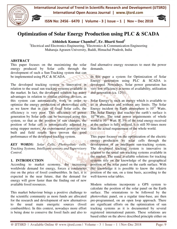
International Journal of Trend in International Open International Open Access Journal | www.ijtsrd.com International Journal of Trend in Scientific Research and Development (IJTSRD) Research and Development (IJTSRD) www.ijtsrd.com ISSN No: 2456 ISSN No: 2456 - 6470 | Volume - 3 | Issue – 1 | Nov Nov – Dec 2018 Optimization of Solar Energy Production Solar Energy Production using PLC PLC & SCADA Abhishek Kumar Chambel Abhishek Kumar Chambel1, Er. Bharti Sood2 Electrical and Electronics Engineering, 2Electronics & Communication Engineering Maharaja Agrasen University, Baddi, Himachal Pradesh, India 1Electrical and Electronics Maharaja Agrasen University, Baddi Electronics & Communication Engineering ABSTRACT This paper focuses on the maximizing the solar energy produced by Solar cells through the development of such a Sun-Tracking system that can be implemented using PLC & SCADA. The developed tracking system is innovative in relation to the usual sun tracking systems available in the market. In fact, the developed solution has many advantages in relation to similar existing this system can automatically work in order to optimize the energy production of photovoltaic cells as we know that in case of fixed Solar cells, the efficiency is very poor. This efficiency of power generation by Solar cells can be increased using this system, so that as the position of sun changes, position of Solar cell is automatically adjusted by using stepper motors. An experimental prototype was built and field results have proven the good performance of the developed tracking system. KEY WORDS: Solar Cells, Photovoltaic cells, Tracking Systems, Intelligent sensors and Supervisory Control. 1.INTRODUCTION According to market economy, the increasing worldwide demand for energy, forces a rise on the price of fossil combustibles. In fact, it is expected in the near future, that the demand for energy will grow faster than the finding out of new available fossil resources. This market behaviour brings a positive challenge to the scientific community as more funds for the research and development of new alternatives to the usual main energetic sources (fossil combustibles). In this context, nowadays more effort is being done to conserve the fossil fuels and also to find alternative energy resources to meet the power demands. In this paper a system for Optimization of Solar Energy generation using PLC & SCADA is developed. Nowadays, Solar power generation has very low efficiency in terms of availability, utilization and generation (ca. 12%). Solar Energy is such an energy which is available to us in abundance and without any limits. The Solar Energy incident on Earth atmosphere is 10 The Solar Energy that reaches the earth’s surface is 1016Watts. The total power re world is 1013 Watt. If, 5% of the total energy received at the surface is fully utilized, it is still 50 times more than the actual requirement of the whole world. This paper focuses on the optimization of the electric energy production by solar development of an intelligent sun The developed tracking system is innovative in relation to the usual sun tracking systems available in the market. The usual available solutions for tracking systems rely on the knowledge of the geographical position of the solar panel on the earth surface. With this knowledge it is possible to know the relative position of the sun, on a time basis, according to well-known solar tables. Modern solutions incorporate a GPS system to calculate the position of the solar panel on the Earth surface. The orientations to be followed by the photovoltaic panel, on a regular time pre-programmed, on an open loop approach. There are significant efforts on the optimization of sun tracking systems as it is documented by several registered international patents. These solutions are based either on the above described principle either on based either on the above described principle either on This paper focuses on the maximizing the solar energy produced by Solar cells through the alternative energy resources to meet the power Tracking system that can In this paper a system for Optimization of Solar Energy generation using PLC & SCADA is , Solar power generation has very low efficiency in terms of availability, utilization The developed tracking system is innovative in relation to the usual sun tracking systems available in the market. In fact, the developed solution has many similar existing devices, as this system can automatically work in order to optimize the energy production of photovoltaic cells as we know that in case of fixed Solar cells, the efficiency is very poor. This efficiency of power generation by Solar cells can be increased using this system, so that as the position of sun changes, the position of Solar cell is automatically adjusted by using stepper motors. An experimental prototype was built and field results have proven the good performance of the developed tracking system. Solar Energy is such an energy which is available to and without any limits. The Solar Energy incident on Earth atmosphere is 1017 Watts. The Solar Energy that reaches the earth’s surface is Watts. The total power requirements of whole Watt. If, 5% of the total energy received at the surface is fully utilized, it is still 50 times more than the actual requirement of the whole world. This paper focuses on the optimization of the electric solar cells through the development of an intelligent sun-tracking system. The developed tracking system is innovative in relation to the usual sun tracking systems available in the market. The usual available solutions for tracking the knowledge of the geographical position of the solar panel on the earth surface. With this knowledge it is possible to know the relative position of the sun, on a time basis, according to the Solar Cells, Photovoltaic cells, igent sensors and Supervisory According to market economy, the increasing worldwide demand for energy, forces a continuous rise on the price of fossil combustibles. In fact, it is expected in the near future, that the demand for energy will grow faster than the finding out of new Modern solutions incorporate a GPS system to calculate the position of the solar panel on the Earth surface. The orientations to be followed by the photovoltaic panel, on a regular time-base, are then programmed, on an open loop approach. There nificant efforts on the optimization of sun tracking systems as it is documented by several registered international patents. These solutions are This market behaviour brings a positive challenge to more funds are allocated for the research and development of new alternatives to the usual main energetic sources (fossil In this context, nowadays more effort is being done to conserve the fossil fuels and also to @ IJTSRD | Available Online @ www.ijtsrd.com www.ijtsrd.com | Volume – 3 | Issue – 1 | Nov-Dec Dec 2018 Page: 9
International Journal of Trend in Scientific Research and Development (IJTSRD) ISSN: 2456 International Journal of Trend in Scientific Research and Development (IJTSRD) ISSN: 2456 International Journal of Trend in Scientific Research and Development (IJTSRD) ISSN: 2456-6470 the quantification of the received solar energy, eithe on the maximization of the solar incident radiation through the use of light concentration lens The solution developed in this paper is innovative related to the above referred approaches as this system is autonomous regarding the information needed to process the optimal orientation and it is intelligent in a way that it monitors, on a real-time base, the photovoltaic energy production and it avoids systematic failures coming from changes on the assumed values (position, initial infrastructure orientation, cleanness of the photovoltaic cells, etc.). 2.SYSTEM DESCRIPTION: A.Overall System Presentation The overall system is presented in fig. 1. The complete strategy is composed by 5 sub- 1.Electro-Mechanical Structure 2.Control Unit 3.Supervisory System 4.Wind-meter 5.Photovoltaic Park. the quantification of the received solar energy, either on the maximization of the solar incident radiation concentration lens. photovoltaic park in order to transfer the new optimal orientation to all PV-production panels. B.Electro-Mechanical Structure The operational subset of the tracking system, named Electro-Mechanical System, is presented in figs 2 and 3. This structure has two DOF, m motors with incorporated encoders; exactly the prescribed path. The was designed using standard industrial Aluminium profiles in order to obtain a simple and economic structure. The mechanical structure is mainly composed by Bosch Profiles and Aluminium plates. The two motorized axis are composed by Step assembled to Aluminium shafts. Figure 2 illustrates the several main components of the mechatronic system: Part n. 6 = Step-Motor to control axi Part n. 7 = Step-Motor to control axis 2; Part n. 8 = Photovoltaic cell (150mmx150mm). ark in order to transfer the new optimal production panels. Mechanical Structure The solution developed in this paper is innovative related to the above referred approaches as this system is autonomous regarding the information needed to process the optimal orientation and it is intelligent in a The operational subset of the tracking system, named Mechanical System, is presented in figs 2 and 3. This structure has two DOF, motorized by stepper encoders; in order to track path. The mechanical system was designed using standard industrial Aluminium profiles in order to obtain a simple and economic time base, the and it avoids systematic failures coming from changes on the assumed values (position, initial infrastructure on, cleanness of the photovoltaic cells, etc.). e is mainly composed by Profiles and Aluminium plates. The two motorized axis are composed by Step-motors assembled to Aluminium shafts. Figure 2 illustrates the several main components of the mechatronic The overall system is presented in fig. 1. The -systems: Motor to control axis 1; Motor to control axis 2; (150mmx150mm). Fig 2 Electromechanical System for Solar Tracking Fig 2 Electromechanical System for Solar Tracking Fig.1 overall system presentation Fig.1 overall system presentation The developed tracking system searches the optimal orientation of a surface, related to the sun incident radiation. The global performance of the system is described below. The planar surface is composed by a photovoltaic cell which is motorized by 2 axis. These two controlled DOF (Degrees of Freedom) are managed by a PLC (Programmable Logic Controller) according to a search program compares the electric power produced by the photovoltaic cell in each correspondent orientation. The maximal power value is stored and the correspondent orientations on both motorized axis are stored. This new optimal orientation of the tracking system is then communicated to the industrial system is then communicated to the industrial The developed tracking system searches the optimal orientation of a surface, related to the sun incident radiation. The global performance of the system is composed by a photovoltaic cell which is motorized by 2-orthogonal axis. These two controlled DOF (Degrees of Freedom) are managed by a PLC (Programmable search program that compares the electric power produced by the in each correspondent orientation. The maximal power value is stored and the motorized axis are Fig.3 Design of Degree of freedom Figure 3 details the two designed degrees of freedom Fig.3 Design of Degree of freedom Figure 3 details the two designed degrees of freedom (DOF). stored. This new optimal orientation of the tracking @ IJTSRD | Available Online @ www.ijtsrd.com www.ijtsrd.com | Volume – 3 | Issue – 1 | Nov-Dec Dec 2018 Page: 10
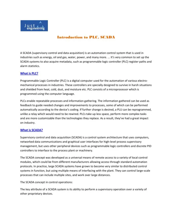
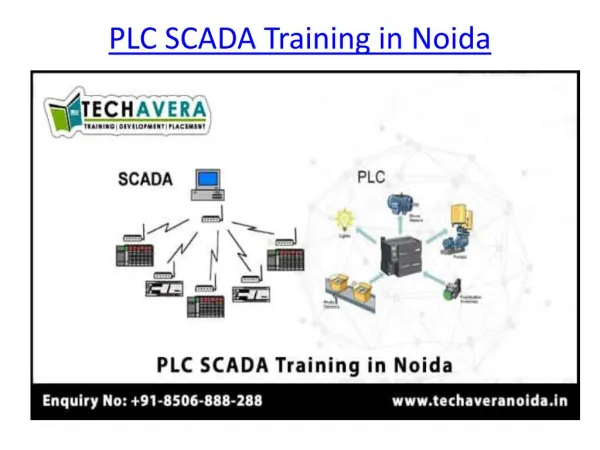
International Journal of Trend in Scientific Research and Development (IJTSRD) ISSN: 2456 International Journal of Trend in Scientific Research and Development (IJTSRD) ISSN: 2456 International Journal of Trend in Scientific Research and Development (IJTSRD) ISSN: 2456-6470 C.Control Unit The control unit consist of PLC Siemens S7 system (Programmable Logic Controller). This control system has the complete operational management of the tracking system. The main tasks performed by the system are: ?Controlling of the two stepper motors; ?Processing the data from both encoders; ?Processing the voltage signal coming from the Solar-Cell; ?Processing the data from the external sensors that informs the system about the hard home position reference. This PLC controls directly the tracking system and commands all other Solar-Panels, from the solar Park, through a Profibus-DP network. Figure 4 shows an example of a solar park with several PV-Panels. Figure 5 illustrates the Profibus network implemented in this study. In the developed supervisory system, the SCADA lication manages the overall system dynamics. The Communication flux between the supervisory system and the control unit is illustrated in fig. 5. The SCADA PC is simultaneously a SCADA server and an internet server, as the implemented SCADA In the developed supervisory application manages the overall system dynamics. The Communication flux between the supervisory system and the control unit is illustrated in fig. 5. The SCADA PC is simultaneously a SCADA server and an internet server, as the implemented SCADA application is web enabled. Siemens S7-300 system (Programmable Logic Controller). This control system has the complete operational management of the tracking system. The main tasks motors; Processing the data from both encoders; oltage signal coming from the Processing the data from the external proximity that informs the system about the hard- LC controls directly the tracking system and Panels, from the solar Park, Figure 4 shows an example of a solar park with Panels. Figure 5 illustrates the Profibus This Figure from a first solar white paper. scale PV Plants,” illustrates the basic architecture and components of a Plant-level Figure 5 This Figure from a first solar white paper. “’Grid-Friendly’ Utility-scale PV Plants, the basic architecture and components of a Control system system 3. EXPERIMENTAL PROTOTYPE A. Physical Description The prototype built followed the design presented in figure 2. This system cell150mmx150mm, Pmax=1,12W, (Polycrystalline Silicon wafer) and the whole structure is made Aluminium alloy. In fig. 6 the global developed prototype is shown. EXPERIMENTAL PROTOTYPE The prototype built followed the design presented in figure 2. This system incorporates incorporates =1,12W, (Polycrystalline a a PV PV- Silicon wafer) and the whole structure is made of Aluminium alloy. In fig. 6 the global developed Fig 4 Solar Panel Power Plant Fig 4 Solar Panel Power Plant D.Supervisory System A SCADA system (Supervisory Control and Data Acquisition) is implemented to monitor and the tracking system. A Supervisory Control and Data Acquisition (SCADA) System is used as an application development tool that enables system integrators to create sophisticated supervisory and control applications for a variety of technological domains, mainly in the industry field. The main feature of a SCADA system is its ability to communicate with control equipment in the field, through the PLC network. As the equipment is monitored and data is recorded, a SCADA application responds according to system logic requirements or operator requests. A SCADA system (Supervisory Control and Data Acquisition) is implemented to monitor and supervise the tracking system. A Supervisory Control and Data Acquisition (SCADA) System is used as an application development tool that enables system integrators to create sophisticated supervisory and control applications for a variety of technological domains, mainly in the industry field. The main feature of a SCADA system is its ability to e with control equipment in the field, through the PLC network. As the equipment is monitored and data is recorded, a SCADA application responds according to system logic requirements or Fig.6 Prototype assembly Fig.6 Prototype assembly The control unit was developed using an industrial 300 PLC Controller). The selected PLC system is a modular The control unit was developed using an industrial Siemens S7-300 PLC Controller). The selected PLC system is a modular device that is constituted by the following modules: device that is constituted by the following modules: (Programmable (Programmable Logic Logic @ IJTSRD | Available Online @ www.ijtsrd.com www.ijtsrd.com | Volume – 3 | Issue – 1 | Nov-Dec Dec 2018 Page: 11
International Journal of Trend in Scientific Research and Development (IJTSRD) ISSN: 2456 International Journal of Trend in Scientific Research and Development (IJTSRD) ISSN: 2456 International Journal of Trend in Scientific Research and Development (IJTSRD) ISSN: 2456-6470 Implemented Control Algorithm The software used for the PLC programming was the Siemens Simatic Step 7, with the Simatic 7 ProdaveV5.5 needed for the communication between the Scada system and the PLC network. The designed control algorithm was implemented using the Ladder B. Implemented Control Algorithm The software used for the PLC programming was the Siemens Simatic Step 7, with the Simatic 7 ProdaveV5.5 needed for the communication between the Scada system and the PLC network. control algorithm was implemented using Diagram language. The developed control algorithm is illustrated in fig. lgorithm is illustrated in fig.8. Slot1 = Power supply PS 307-2A Slot2 = Processor CPU 315-2DP Slot4 = Communication module CP 342 Slot5 = Digital card DI8/DO8xDC24V/0,5A Slot6 = Analog card AI8 x12bit Slot7 = Analog card AO4 x12bit Slot8 = FM card – Counter Module (FM350) Slot9 = FM card – Counter Module (FM350) Slot10 = FM card – Stepper Motor (FM353) Slot11 = FM card – Stepper Motor (FM353) Additionally, the PLC-tracker has a modem for GSM communication that provides the system capacity to communicate through the mobile phone network. The driving unit is composed by two motorized axis, with the following characteristics: 1. Axis 1 ?Step motor: Nanotec ST4018L0804, 50Ncm; ?Opt. Encoder: HP HEDL-5540 A14, 500 Pulses ?Coupling unit: Oldham D5 ?Proximity sensor: Omrom EA2 M8 PNP 2. Axis 2 ?Step motor: Nanotec ST5918L1008, 170Ncm; ?Gear box: Nanotec PLE40-1S-4 ?Opt. Encoder: HP HEDL-5540 A14, 500 Pulses ?Coupling unit: Oldham D25 ?Proximity sensor: Omron EA2 M8 PNP Figure 7 details the electro-mechanical structure of the developed sun-tracker system. Slot4 = Communication module CP 342 -5 Slot5 = Digital card DI8/DO8xDC24V/0,5A Counter Module (FM350) Counter Module (FM350) (FM353) Stepper Motor (FM353) tracker has a modem for GSM communication that provides the system capacity to communicate through the mobile phone network. The driving unit is composed by two motorized axis, Step motor: Nanotec ST4018L0804, 50Ncm; 5540 A14, 500 Pulses Proximity sensor: Omrom EA2 M8 PNP Step motor: Nanotec ST5918L1008, 170Ncm; 5540 A14, 500 Pulses Proximity sensor: Omron EA2 M8 PNP mechanical structure of Fig.8 Control Algorithm for the Tracking System Fig.8 Control Algorithm for the Tracking System A short description of the tasks performed by the tracker controller, regarding the above referred algorithm, is described below: Box0: After reset is activated, the system stores the PV-power generated in the actual position, P the variable Pin. The system null position. It moves until it finds the hard position (both external proximity sensors on). In this position the system assumes the absolute orientation angles for both axis equal zero ( maximal Power, Pmax is set to zero. Both C1, C2, are loaded; A short description of the tasks performed by the tracker controller, regarding the above referred described below: Box0: After reset is activated, the system stores the power generated in the actual position, Pactual, in the variable Pin. The system searches its reference- null position. It moves until it finds the hard-home position (both external proximity sensors on). In this position the system assumes the absolute orientation angles for both axis equal zero (α1 = α2 = 0). The maximal Power, Pmax is set to zero. Bothcounters, Fig 7 Prototype Assembly: Solar panel Solar panel @ IJTSRD | Available Online @ www.ijtsrd.com www.ijtsrd.com | Volume – 3 | Issue – 1 | Nov-Dec Dec 2018 Page: 12
International Journal of Trend in Scientific Research and Development (IJTSRD) ISSN: 2456 International Journal of Trend in Scientific Research and Development (IJTSRD) ISSN: 2456 International Journal of Trend in Scientific Research and Development (IJTSRD) ISSN: 2456-6470 Box1: After start is activated, the system initiates the search for the maximal power generated in axis 1, with an angle increment α10. The system stores the power generated in variable P1. Box2: If P1 < P max, the system goes to Box 4, and follows for a new position; Box3: If P1 > P max, this position is stored in the variables: α1max, α2max. The max Power value, P max is actualized with the new Power value P1; Box4: Counter for axis 1 is updated; Box5: After all orientations for axis 1 are evaluated, regarding a fixed orientation for axis 2, axis 2 is positioned in a new position, with an angle increment α20, and axis 1 returns to its initial position system re-initiates the search for the optimal orientation of axis 1, regarding the new position of axis 2. The information flux returns to box 1. Box6: After all orientations for axis 1 are evaluated, regarding all different positions of axis 2, the system compares the maximal power found (P initial Power generated, before the search process had begun (Pin). If the new Power value is greater than a pre-defined gain, this new correspondent orientation (α1max, α2max) is sent to all park panels. If the power gain is not enough, the new found position is not to follow by the other PV-panels. Box7: After a pre-defined time interval (K) the tracker system initiates a new complete search process in both axis. The information flux returns to box 0. C. SCADA Supervisory System The SCADA system used to implement this monitoring and control strategy permits the access to the application, depending on the user’s responsibility degree. In this paper we developed three user levels: Operators, Supervisors and Administrators. Several SCADA menus were built. The main characteristic of a SCADA Menu is to be s explicit and quick on transmitting the information to the operator or to the System administrator. One of the developed Graphical User Interfaces (GUI) is shown in fig 9. activated, the system initiates the search for the maximal power generated in axis 1, 10. The system stores the max, the system goes to Box 4, and max, this position is stored in the Power value, Fig 9 SCADA view of Solar Tracker Fig 9 SCADA view of Solar Tracker max is actualized with the new Power value P1; As this SCADA platform is web enabled, all the GUI line accessible through the As this SCADA platform is web enabled, all the GUI displayed data is also on-line accessible through the internet. In fig. 9 it is shown the developed main menu for the sun-tracker system. The on-line available information, referring actual data from the position for both axis, actual PV max. daily PV-power generated, actual efficiency ratio. 4.CONCLUSIONS The developed tracker for sun radiation worked very well. The increase in power generation, in relation to other Solar Energy-systems, without tracking devices, is of similar magnitude (ca. 25%) as for other usual tracking solutions. However, this system h advantage, as it measures exactly the co variable: the actual Solar power Note: If we can just utilize 5% of the total available solar energy on earth surface, it will be 50 times the energy which is required by the whole w this way, there will never be any shortage of power supply except in case of non sunlight. In such case, the other sources of power can be used so that we use as much less fossil fuels as possible. REFERENCES JOURNAL / CONFERENCE PAPERS 1.Bajpai P, Kumar S, “Design, development and performance test of an automatic two tracker system”, Annual IEEE Conference Publication, India Conference (INDCON) 2011, Electr. Eng. Dept., IIT Kharagpur, Kharagpur, 16 18 Dec. 2011, 1–6. 2.Esram T, Kimball JW, Krein PT, Chapman PL, Midya P, ”Dynamic maximum power point Midya P, ”Dynamic maximum power point Box5: After all orientations for axis 1 are evaluated, ntation for axis 2, axis 2 is positioned in a new position, with an angle increment 20, and axis 1 returns to its initial position α1=0. The initiates the search for the optimal orientation of axis 1, regarding the new position of formation flux returns to box 1. In fig. 9 it is shown the developed main menu for the line available information, referring actual data from the tracker unit is: actual for both axis, actual PV-power generated, power generated, actual efficiency Box6: After all orientations for axis 1 are evaluated, regarding all different positions of axis 2, the system compares the maximal power found (P max) with the initial Power generated, before the search process had Pin). If the new Power value is greater than a defined gain, this new correspondent orientation 2max) is sent to all park panels. If the power gain is not enough, the new found position is The developed tracker for sun radiation worked very well. The increase in power generation, in relation to systems, without tracking devices, is of similar magnitude (ca. 25%) as for other usual tracking solutions. However, this system has a relative advantage, as it measures exactly the controlled Solar power generation. If we can just utilize 5% of the total available solar energy on earth surface, it will be 50 times the energy which is required by the whole world. And in this way, there will never be any shortage of power supply except in case of non-availability of direct interval (K) the tracker system initiates a new complete search process in both axis. The information flux returns to box 0. The SCADA system used to implement this monitoring and control strategy permits the selective access to the application, depending on the user’s responsibility degree. In this paper we developed three user levels: Operators, Supervisors and In such case, the other sources of power can be used so that we use as much less fossil fuels as possible. ONFERENCE PAPERS Bajpai P, Kumar S, “Design, development and performance test of an automatic two-axis solar tracker system”, Annual IEEE Conference Publication, India Conference (INDCON) 2011, Electr. Eng. Dept., IIT Kharagpur, Kharagpur, 16- Several SCADA menus were built. The main characteristic of a SCADA Menu is to be simple, quick on transmitting the information to the operator or to the System administrator. Esram T, Kimball JW, Krein PT, Chapman PL, Interfaces (GUI) @ IJTSRD | Available Online @ www.ijtsrd.com www.ijtsrd.com | Volume – 3 | Issue – 1 | Nov-Dec Dec 2018 Page: 13
International Journal of Trend in Scientific Research and Development (IJTSRD) ISSN: 2456 International Journal of Trend in Scientific Research and Development (IJTSRD) ISSN: 2456 International Journal of Trend in Scientific Research and Development (IJTSRD) ISSN: 2456-6470 tracking of photovoltaic arrays using ripple correlation control”, IEEE Transactions. 21(5), Illinois Univ., Urbana, IL, 1282–1291. 3.Feng-run Liu, Le Xiao, Wen-jia Li,” The design of automatic solar tracking system for solar cell”, IEEE 2nd International Conference on Artificial Intelligence, Management Science and Electronic Commerce (AIMSEC) 2011; North China University of Technology, China, 8- 4451–4454 4.Huifeng Jiao, Jianzhong Fu, Yuchun Li, Jintao Lai, “Design of automatic two-axis sun system”, IEEE International Conference on Mechanic Automation and Control Engineering (MACE) 2010, Dept. of Mech. Eng., Zhejia Univ., China, 26-28 June 2010, 2323 5.Khan MTA, Tanzil SMS, Rahman R, Alam SMS.” Design and construction of an automatic solar tracking system”, IEEE 6th International Conference on Electrical Engineering (ICECE), 2010, Dept. of Ele Engineering (ICECE), 2010, Dept. of Electr. & tracking of photovoltaic arrays using ripple correlation control”, IEEE Transactions. 2006; Electron. Eng., [7] Simatic Net Profibus/ FMS. SIEMENS 12/2001. 6.System Software for S7 Reference Manual, A5E00069892-02 7.Simatic S7 Prodave S7 – PCs, SIEMENS, 2001 8.Simatic S7-300 – Ladder Logic (LAD) for S7 300, SIEMENS, 2001. 9.WinCC-Advanced/Pro for SCADA Systems 10.Weiping Luo ,” A solar panels automatic tracking system based on Omron PLC”, Asian Control Conference(ASCC)2009, Wuhan University of Science & Engineering, China, 27 2009,1611-1614. 11.Zhang Bao-jian, Gao Guo li.”Designment of automatic tracking system of solar energy system”, Conference on Industrial Mechatronics and Automation, 2010, Comput. Sci. Dept., Henan Inst. of Sci. & Technol., China, 30 2010689–691. 7] Simatic Net – NCM S7 for Profibus/ FMS. SIEMENS 12/2001. IL, Sept. 2006, System Software for S7-300 and S7-400 – Reference Manual, SIEMENS SIEMENS 08/2000; 08/2000; jia Li,” The design of automatic solar tracking system for solar cell”, IEEE 2nd International Conference on Artificial Intelligence, Management Science and Electronic Commerce (AIMSEC) 2011; North China – Toolbox for PGs and Ladder Logic (LAD) for S7- -10 Aug. 2011, Advanced/Pro for SCADA Systems Huifeng Jiao, Jianzhong Fu, Yuchun Li, Jintao Weiping Luo ,” A solar panels automatic tracking system based on Omron PLC”, Asian Control Conference(ASCC)2009, Wuhan University of ng, China, 27-29 Aug. axis sun-tracking system”, IEEE International Conference on Mechanic Automation and Control Engineering (MACE) 2010, Dept. of Mech. Eng., Zhejiang 28 June 2010, 2323–2326. jian, Gao Guo-hong, Zhu Yan- li.”Designment of automatic tracking system of solar energy system”, Conference on Industrial Mechatronics and Automation, 2010, Comput. Sci. Dept., Henan st. of Sci. & Technol., China, 30-31 May Khan MTA, Tanzil SMS, Rahman R, Alam SMS.” Design and construction of an automatic solar tracking system”, IEEE 6th International Conference on Electrical 2nd 2nd International International and and Computer Computer @ IJTSRD | Available Online @ www.ijtsrd.com www.ijtsrd.com | Volume – 3 | Issue – 1 | Nov-Dec Dec 2018 Page: 14