Download
1 / 8
80 likes | 97 Vues
Home automation is the way of automating the routine activities and the activities which require physical effort. Though much of the effort into automation systems development has been put into reducing the physical effort and automating home management systems, there is only very limited effort has been put in development of home automation systems which will aid and assist senior citizens. So in this study, a simple ON OFF activity is voice automated and is much focused on aiding senior citizens, because this simple action is most common and effort taking in many senses. The automation system developed has been designed to have a hand held device as well which has a built in microphone system which can be used to say commands without the need to move to the switch board. V. Ram Kumar "Voice Operated Home Automation for Senior Citizens" Published in International Journal of Trend in Scientific Research and Development (ijtsrd), ISSN: 2456-6470, Volume-3 | Issue-1 , December 2018, URL: https://www.ijtsrd.com/papers/ijtsrd18923.pdf Paper URL: http://www.ijtsrd.com/engineering/other/18923/voice-operated-home-automation-for-senior-citizens/v-ram-kumar<br>

E N D
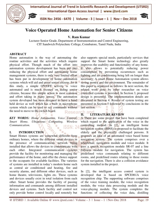
International Journal of Trend in International Open International Open Access Journal | www.ijtsrd.com International Journal of Trend in Scientific Research and Development (IJTSRD) Research and Development (IJTSRD) www.ijtsrd.com ISSN No: 2456 ISSN No: 2456 - 6470 | Volume - 3 | Issue – 1 | Nov Nov – Dec 2018 Voice Operated Home Automation Voice Operated Home Automation for Senior Citizens Senior Citizens V. Ram Kumar Department of Instrumentation and Control Engineering, Instrumentation and Control Engineering, Lecturer Senior Grade, Dep CIT Sandwich Polytechnic College IT Sandwich Polytechnic College, Coimbatore,Tamil Nadu, India India ABSTRACT Home automation is the way of automating the routine activities and the activities which require physical effort. Though much of the effort into automation systems development has been put into reducing the physical effort and automating home management systems, there is only very limited effort has been put in development of home automation systems which will aid and assist senior citizens. So in this study, a simple ON/OFF activity is voice automated and is much focused on aiding senior citizens, because this simple action is most common and effort taking in many senses. The automation system developed has been designed to have a hand held device as well which has a built in microphone system which can be used to say commands without the need to move to the switch board. KEY WORDS: Home Automation, Voice Control, Smart Home, Ubiquitous Computing, Wireless Communication. I. INTRODUCTION Smart Homes systems are somewhat different from ordinary homes, where the different smart devices in the presence of communications network being installed that allows the devices to communicate with each other. Integrated communication systems provide the facility for monitoring and managing the performance of the home, and offer the choice support to the occupants for available facilities. The varieties of systems are installed in today’s modern home such as central air conditioned and heating, fire and security alarms, and different other devices, such as home theatre, televisions, lights etc. These systems and devices usually exist in total isolation from each other. Smart home provides the facility of passing information and commands among different installed devices and systems. Such facility and control not only provide better control locally and remotely but only provide better control locally and remotely but also supports special needs, particularly services that support the Smart home technology also greatly improves the usability and functionality of any home. It also allows to potentially reducing power consumption by preventing occurrences such as lighting and air conditioning being left on longer than necessary. A smart Home Automation system allows saving money and the environment. The remainder of this paper is organized as follows: In next section, the related work done by other researcher on voice controlled systems is provided. In Section 3, proposed design is presented. The implementation details are discussed in Section 4. Results of system testing are presented in Section 5 followed by conclusions in the last section. II. LITERATURE REVIEW A There are some project that have been completed which regard to the application of the voice in the controlling method. In [1], an intelligent home navigation system (IHNS) is proposed to facilitate the elderly and the physically challenged persons. It proposes an idea of an automated voice based home navigation system. The system comprises over a wheelchair, navigation module and voice module. It uses a speech recognition module SR follower module for navigation. The system has predefined voice commands relating rooms, and predefined routes relating to those rooms for the navigation. There is also a collision avoidance system installed in the project. In [2], the intelligent access control system is developed that is based on SPC recognition chip. The supporting software comprises of the voice training module, the voice recognition module, the voice data processing module and the voice-playing module. The system completes the functions of collecting the voice data, dist functions of collecting the voice data, distilling Home automation is the way of automating the routine activities and the activities which require physical effort. Though much of the effort into automation systems development has been put into reducing the physical effort and automating home gement systems, there is only very limited effort has been put in development of home automation systems which will aid and assist senior citizens. So in this study, a simple ON/OFF activity is voice automated and is much focused on aiding senior because this simple action is most common and effort taking in many senses. The automation system developed has been designed to have a hand held device as well which has a built in microphone system which can be used to say commands without special needs, particularly services that Smart home technology also greatly improves the usability and functionality of any home. It also allows to potentially reducing power on by preventing occurrences such as lighting and air conditioning being left on longer than necessary. A smart Home Automation system allows saving money and the environment. The remainder of this paper is organized as follows: In next section, the d work done by other researcher on voice controlled systems is provided. In Section 3, proposed design is presented. The implementation details are discussed in Section 4. Results of system testing are presented in Section 5 followed by conclusions in the LITERATURE REVIEW ct that have been completed Home Automation, Voice Control, Smart Home, Ubiquitous Computing, Wireless which regard to the application of the voice in the controlling method. In [1], an intelligent home navigation system (IHNS) is proposed to facilitate the elderly and the physically challenged persons. It automated voice based home navigation system. The system comprises over a wheelchair, navigation module and voice module. It uses a speech recognition module SR-07 and a line follower module for navigation. The system has predefined voice commands relating to different rooms, and predefined routes relating to those rooms for the navigation. There is also a collision avoidance system installed in the project. Smart Homes systems are somewhat different from ordinary homes, where the different smart devices in cations network being installed that allows the devices to communicate with each other. Integrated communication systems provide the facility for monitoring and managing the performance of the home, and offer the choice support le facilities. The varieties of systems are installed in today’s modern home such as central air conditioned and heating, fire and security alarms, and different other devices, such as home theatre, televisions, lights etc. These systems y exist in total isolation from each other. Smart home provides the facility of passing information and commands among different installed devices and systems. Such facility and control not In [2], the intelligent access control system is developed that is based on SPCE061A voice recognition chip. The supporting software comprises of the voice training module, the voice recognition module, the voice data processing module and the playing module. The system completes the @ IJTSRD | Available Online @ www.ijtsrd.com www.ijtsrd.com | Volume – 3 | Issue – 1 | Nov-Dec Dec 2018 Page: 19
International Journal of Trend in Scientific Research and Development (IJTSRD) ISSN: 2456 International Journal of Trend in Scientific Research and Development (IJTSRD) ISSN: 2456 International Journal of Trend in Scientific Research and Development (IJTSRD) ISSN: 2456-6470 character, special voice recognition and voice playing in terms of initializing the system a Table1. Chart comparing the various voice control systems available in the market. Automated Voice based Home Navigation Navigation Module Voice Module Collision Avoidance Data Processing Voice Playing Speaker Dependent system Finite inductive Sequence (FIS) system The system presented in [4] is the voice controlled smart house. It works on the predefined set of voice commands for the defined areas in a house. The new commands can be added in as required. FIS, a pattern processing technology, is used that allows processing of complex patterns as experienced in speech and vision. The project Voice Controlled House Automation System (VCHAS) uses an RF module and AVR Microcontroller. The previous systems have not been made handheld, and so do not require an RF module, since they do not employ a remote. In the developed since they do not employ a remote. In the developed character, special voice recognition and voice playing in terms of initializing the system and the identification training. Chart comparing the various voice control systems available in the market. Chart comparing the various voice control systems available in the market. Automated Voice based Home Navigation System Control System ✔ ✔ ✔ ✘ ✘ ✔ Intelligent Access Voice Activated Wheelchair ✘ ✔ ✘ ✘ ✘ ✔ Voice Controlled Smart House ✘ ✔ ✘ ✘ ✘ ✘ Activated Wheelchair ✘ ✔ ✘ ✔ ✔ ✔ ✘ ✘ ✘ ✔ The system presented in [4] is the voice controlled smart house. It works on the predefined set of voice commands for the defined areas in a house. The new project, device is made more portable, low cost and easy to use, by making it a hand-held device. project, device is made more portable, low cost and easy to use, by making it a hand III. PROPOSED DESIGN The system is divided into three parts: block, controlling block and receiving block 2.1. Basic Design Blocks The system is divided into three basic design blocks namely, 1.Transmission block 2.Controlling block 3.Receiving block PROPOSED DESIGN s divided into three parts: transmission receiving block. required. FIS, a pattern processing technology, is used that allows processing of complex patterns as experienced in speech and The project Voice Controlled House Automation System (VCHAS) uses an RF module and AVR The system is divided into three basic design blocks tems have not been made handheld, and so do not require an RF module, Figure1. Transmission Block 2.1.1. Transmitting block 2.1.1.1. Voice input block The Voice input block takes the voice of the speaker as an input signal, as the name implies. This block comprises of an input device, which might be a sensor, to detect voice as an analog input to the sensor, to detect voice as an analog input to the system. The analog input signal is then passed onto the block responsible for receiving input signal to match input signals and initiate the required tasks of appliance control. required tasks of appliance control. The Voice input block takes the voice of the speaker as an input signal, as the name implies. This block comprises of an input device, which might be a system. The analog input signal is then passed onto e block responsible for receiving and processing the to match input signals and initiate the @ IJTSRD | Available Online @ www.ijtsrd.com www.ijtsrd.com | Volume – 3 | Issue – 1 | Nov-Dec Dec 2018 Page: 20
International Journal of Trend in Scientific Research and Development (IJTSRD) ISSN: 2456 International Journal of Trend in Scientific Research and Development (IJTSRD) ISSN: 2456 International Journal of Trend in Scientific Research and Development (IJTSRD) ISSN: 2456-6470 2.1.1.7. Coding block There is a need to code signal so that it become possible to interface the upper part of circuit with the transmitting block. 2.1.1.8. Transmitting block It is to send signal from one point to the point of reception using suitable transmission technolo 2.1.2. Controlling block 2.1.2.1. Receiving block This block will be used to receive signal serially from one point to the other. 2.1.2.2. Decoding block A decoder is used at receiver, almost in a manner similar to the coding block, to interface receiv the rest of the circuit. 2.1.2.3. Controller block The controller block is responsible for interfacing the rest of the circuitry with the lower part of the circuit; otherwise there is no other medium of creating a connection of the received input with the safety section, and the switching block. The controlling block handles the processes to be able to select which appliance is supposed to be operated. 2.1.1.2 Storage block When the signal processing block is trained, through the manual training block, space to store input commands is required. Space is needed to retain predefined commands as addresses in the memory, and later match the spoken commands with the predefined commands to perform a function. In this block, first predefined commands are saved and later they are used for matching with the voice input to perform a defined task.2.1.1.5. Controller block The controller block is responsible for interfacing the rest of the circuitry with the upper part of the circuit; otherwise there is no other medium of creatin connection of the input and storage blocks with the display section, and the coding block. 2.1.1.6. Display block The display block is included, since it was needed to make the system more users friendly and easily accessible to all. The display block command that have spoken, so that they can also be visualized, and also know the function that is going be performed. In case of errors, it also notifies about the error. It is a medium of sense created to help the users. When the signal processing block is trained, through the manual training block, e input commands is required. Space is needed to retain predefined commands as addresses in the memory, and later match the spoken commands with the predefined commands to perform a function. In this block, first predefined commands are saved y are used for matching with the voice There is a need to code signal so that it become possible to interface the upper part of circuit with the It is to send signal from one point to the point of reception using suitable transmission technology. 2.1.1.5. Controller The controller block is responsible for interfacing the rest of the circuitry with the upper part of the circuit; otherwise there is no other medium of creating a connection of the input and storage blocks with the This block will be used to receive signal serially from A decoder is used at receiver, almost in a manner similar to the coding block, to interface receiver with The display block is included, since it was needed to make the system more users friendly and easily accessible to all. The display block displays the command that have spoken, so that they can also be visualized, and also know the function that is goingto be performed. In case of errors, it also notifies about the error. It is a medium of sense created to help the The controller block is responsible for interfacing the rest of the circuitry with the lower part of the circuit; otherwise there is no other medium of creating a the received input with the safety section, and the switching block. The controlling block handles the processes to be able to select which appliance is Figure 2.Receiving and Controlling Block Figure 2.Receiving and Controlling Block 2.1.2.4. Safety block It is necessary to create a safety circuit, so that the system is protected against damage, in case of any back EMF or high voltage etc. this block is responsible for a no-physical-connection route towards the rest of the circuit, preventing damage due to physical connections. 2.1.3. Receiving block The entire receiving block is responsible for switching and operating the appliances or devices. and operating the appliances or devices. 2.1.3.1. Switching block The switching block is used so that it can be decided whether the device is to be switched ON or OFF, according to the signal received by the controlling circuit. 2.1.3.2. Appliance block This block is the end of the system, and this is where the home appliances will operate. Details VCHAS is a smar burgeoning industry has spawned a choice selection burgeoning industry has spawned a choice selection It is necessary to create a safety circuit, so that the system is protected against damage, in case of any back EMF or high voltage etc. this block is The switching block is used so that it can be decided the device is to be switched ON or OFF, according to the signal received by the controlling connection route , preventing damage due This block is the end of the system, and this is where the home appliances will operate.3. Implementation Details VCHAS is a smart home system. This The entire receiving block is responsible for switching @ IJTSRD | Available Online @ www.ijtsrd.com www.ijtsrd.com | Volume – 3 | Issue – 1 | Nov-Dec Dec 2018 Page: 21
International Journal of Trend in Scientific Research and Development (IJTSRD) ISSN: 2456 International Journal of Trend in Scientific Research and Development (IJTSRD) ISSN: 2456 International Journal of Trend in Scientific Research and Development (IJTSRD) ISSN: 2456-6470 3.2. Voice based controlling requirements 3.2. Voice based controlling requirements 3.2.1. Speech Recognition Speech recognition is becoming the method of choice for controlling appliances, toys, tools, computers and robotics. The voice controlled appliances like computer, TV, lighting system, security system, etc. become easier to use, while increasing the effici and effectiveness ofworking with that device. Figure 4.Architecture of Receiving Circuit Figure 4.Architecture of Receiving Circuit of products from several respected manufacturers. Home automation systems usually work on wireless technology, but very few are actually voice controlled. The proposed system is an inno this technology where the VCHAS is introduced to be more compatible and convenient by bringing a hand held device to the consumers. VCHAS uses a transducer, keyboard, Integrated circuit for speech recognition, RF module, and AVR microcontroller primarily. Additional equipment such as the LCD is commonly added to expand the home automation systems capabilities and make it more users friendly. 3.1.System Architecture The system depends upon a transmitting section and a receiving section, that is apparent in system architecture diagram (refer to figure 3). Figure 3.Architecture of Transmitting Circuit Figure 3.Architecture of Transmitting Circuit of products from several respected manufacturers. Home automation systems usually work on wireless technology, but very few are actually voice controlled. The proposed system is an innovation to this technology where the VCHAS is introduced to be more compatible and convenient by bringing a hand- held device to the consumers. VCHAS uses a transducer, keyboard, Integrated circuit for speech recognition, RF module, and AVR microcontroller rimarily. Additional equipment such as the LCD is commonly added to expand the home automation capabilities and make it more users friendly. Speech recognition is becoming the method of choice for controlling appliances, toys, tools, computers and robotics. The voice controlled appliances like computer, TV, lighting system, security system, etc. become easier to use, while increasing the efficiency working with that device. The system depends upon a transmitting section and a g section, that is apparent in system Different Speech recognition integrated circuits are available in the market. The HM2007 speech cuit is one of them that provide the options of recognizing either forty .96 second words or twenty 1.92 second words. It allows either the .96 second word length (40 word vocabulary) or the 1.92 second word length (20 word vocabulary). The HM2007 stores the "trained" word patterns used for recognition in external memory. For memory, the circuit uses an on board 8K x 8 static RAM supported by coin battery. The main board has a that provides backup power to the Different Speech recognition integrated circuits are available in the market. The HM2007 speech recognition integrated circuit is one of them that provide the options of recognizing either forty .96 second words or twenty 1.92 second words. It allows either the .96 second word length (40 word vocabulary) or the 1.92 second word length (20 word vocabulary). The HM2007 stores t patterns used for recognition in external memory. For memory, the circuit uses an on board 8K x 8 static RAM supported by coin battery. The main board has a coin battery holderthat provides backup power to the static ram when the main circuit is turned off. This keeps all the trained words safely stored in memory (SRAM) so the circuit does not have to be retrained every time it is turned on [7]. 3.2.2. Speaker Dependency Speech recognition is classified into two categories, speaker dependent and speaker independent. ent and speaker independent. The system is based upon the use of voice as a physical parameter, which is later conceive command by the VCHAS. The question is about interfacing voice commands with the rest of the system. To move ahead with the process, a transducer is used, for the purpose of converting physical parameter of voice into an electrical signal. HM2007 (Speech Recognition Chip) [6] is available with a pin, to which a microphone can be directly connected, for the purpose of speaking the command verbally into the circuit. The system is based upon the use of voice as a physical parameter, which is later conceived as a command by the VCHAS. The question is about interfacing voice commands with the rest of the system. To move ahead with the process, a transducer is used, for the purpose of converting physical parameter of voice into an electrical signal. HM2007 eech Recognition Chip) [6] is available with a pin, to which a microphone can be directly connected, for the purpose of speaking the command verbally into rcuit is turned off. This keeps all the trained words safely stored in memory (SRAM) so the circuit does not have to be retrained Speech recognition is classified into two categories, @ IJTSRD | Available Online @ www.ijtsrd.com www.ijtsrd.com | Volume – 3 | Issue – 1 | Nov-Dec Dec 2018 Page: 22
International Journal of Trend in Scientific Research and Development (IJTSRD) ISSN: 2456 International Journal of Trend in Scientific Research and Development (IJTSRD) ISSN: 2456 International Journal of Trend in Scientific Research and Development (IJTSRD) ISSN: 2456-6470 Speaker independent is a system trained to respond to a word regardless of who speaks. Therefore the system must respond to a large variety of speech patterns, inflections and enunciation's of the target word. The command word count is usually lower than the speaker dependent however high accuracy can still be maintained within processing limits. Industrial requirements more often need speaker independent voice systems. Speaker dependent systems are trained by the individual who will be using the system. These systems are capable of achieving a high command count and better than 95% accuracy for word recognition. The drawback to this approach is the system only responds accurately only to the individual who trained the system. This is the most common approach employed in software for personal computers. VCHAS employs the speaker dependent system, since it is one of the major characteristics of the IC HM2007 chip used. 3.2.3. Recognition Style One of the constraints of speech recognition systems is the style of speech they can recognize. There are three different styles of speech that are isolated, connected and continuous [7]. Isolated speech recognition systems – handle words that are spoken separately. This is the most common speech recognition systems. The user must pause between each word and command spoken. Connected – It is a half-way point between isolated word and continuous speech recognition. It allows users to speak multiple words. Continuous – It is the natural conversational speech people are accustomed to in everyday life. It is extremely difficult for a recognizer to shift through the text as the words tend to merge together. Isolated speech recognition system is another feature, of IC HM2007, and a characteristic of the system. 3.3. Training voice recognition module Before utilization of the system, it is required that the user should train the system according to their choice of words, to provide better accessibility to the user. The circuit can be fed with the commands desired by the user, and for that, HM2007 is interfaced with a microphone, keypad and 7-segment display, thus increasing user compatibility. Speaker independent is a system trained to respond to a word regardless of who speaks. Therefore the system must respond to a large variety of speech patterns, inflections and enunciation's of the target count is usually lower than the speaker dependent however high accuracy can still be maintained within processing limits. Industrial requirements more often need speaker independent When the system is switched ON to be trained, the 7- segment display shows “00” and the LED are turned there is a need to record a command at number “24”, so the digits “24” on the keypad are When the system is switched ON to be trained, the 7 segment display shows “00” and the LED ON. Suppose there is a need to record a command at number “24”, so the digits “24” on the keypad are pressed, and the LED turns OFF. Now to train “#” is pressed, thus switching the LED ON. When the LED turns ON, it is time to speak command into the Microphone verbally, within 1.92 seconds (20 words). When the LED starts blinking, it means the word is being stored into VCHAS is successfully trained for the particular voice command, to be used again and again in the future. CLEAR ALL pattern is also available. If the key is pressed with number “99” and later “CLEAR” is pressed, all previous storage is erased [6]. 3.4. The Voice input At the time of storing voice input as commands to the system, a 13 bit address is passed onto the memory, SRAM where the addresses are defined, containing information about what commands are stored where in the memory. Later, when the commands are spoken into the microphone, an 8 bit of data is sent to the SRAM from the HM2007 and command for the address where it is stored. If the input data of the command does not match the commands, then an error signal is generated, otherwise the command is passed onto the latch Figure 5.Training the voice Recognition Module. Figure 5.Training the voice Recognition Module. OFF. Now to train “#” is pressed, thus switching the LED ON. When the LED turns ON, it is time to speak ne verbally, within 1.92 seconds (20 words). When the LED starts blinking, it stored into the SRAM and VCHAS is successfully trained for the particular voice command, to be used again and again in the Speaker dependent systems are trained by the o will be using the system. These systems are capable of achieving a high command count and better than 95% accuracy for word recognition. The drawback to this approach is the system only responds accurately only to the individual o available. If the key is his is the most common pressed with number “99” and later “CLEAR” is approach employed in software for personal computers. VCHAS employs the speaker dependent system, since it is one of the major characteristics of is erased [6]. At the time of storing voice input as commands to the system, a 13 bit address is passed onto the memory, e addresses are defined, containing information about what commands are stored where gnition systems is the style of speech they can recognize. There are three different styles of speech that are isolated, the commands are spoken into the microphone, an 8 bit of data is sent to the SRAM from the HM2007 and the RAM matches the where it is stored. If the – It can only input data of the command does not match the stored , then an error signal is generated, otherwise the command is passed onto the latch. handle words that are spoken separately. This is the st common speech recognition systems. The user must pause between each word and command spoken. way point between isolated word and continuous speech recognition. It allows ral conversational speech people are accustomed to in everyday life. It is extremely difficult for a recognizer to shift through the text as the words tend to merge together. Isolated speech recognition system is another feature, cteristic of the system. 3.3. Training voice recognition module Before utilization of the system, it is required that the user should train the system according to their choice provide better accessibility to the user. th the commands desired by 3.5. Microcontroller interfacing with LCD and Encoder After the data is matched, the 8 bit of data is stored onto the latch, to be sent to the microcontroller. The Microcontroller interfaces a 16 x 2 LCD and an Microcontroller interfaces a 16 x 2 LCD and an Microcontroller interfacing with LCD and After the data is matched, the 8 bit of data is stored onto the latch, to be sent to the microcontroller. The is interfaced with a segment display, thus @ IJTSRD | Available Online @ www.ijtsrd.com www.ijtsrd.com | Volume – 3 | Issue – 1 | Nov-Dec Dec 2018 Page: 23
International Journal of Trend in Scientific Research and Development (IJTSRD) ISSN: 2456 International Journal of Trend in Scientific Research and Development (IJTSRD) ISSN: 2456 International Journal of Trend in Scientific Research and Development (IJTSRD) ISSN: 2456-6470 3.10.1. Hand Held Device The voice controlled home automation system, has a unique design, where it uses a handheld transmitter section. The device is handheld and more accessible to the user. As the user may be a disabled person, or a patient, he can easily use the remote and speak his desired command. The handheld technique is potentially a new idea, and has not been previously implemented; hence implementation from the previous innovations of the system. Figure 6.Schematic of h Figure 6.Schematic of handheld device. encoder to the circuit [8]. The LCD displays the command that have microcontroller was previously programmed to display certain commands for certain numbers. 12 bits of data are sent from the microcontroller to the encoder. Encoder converts received parallel data (of which 8 bits are of address and 4 bits are of data) into serial and sends to the transmitter [9]. 3.6. RF module The RF module consists of a transmitter and a receiver. It will be operating within a range of 433MHz. The transmitter will transmit 12 bits of data serially, bit by bit, to the receiver. The receiver will receive the data one bit at a time, and serially. 3.7. Microcontroller Interfacing with Decoder and Buffer At receiver, the decoder decodes the serial addresses and data received into parallel data and sends them to output data pins. The received data is compared with the local addresses three times. The data is decoded only in case no error or unmatched codes are found. High signal is generated at VT pin in case of a valid transmission. The 4 bits of data and 8 bits of address are now sent to the microcontroller. From the microcontroller the data is sent to the buffer. The buffer acts as a driving for current in the 3.8. Safety Circuit The current is now passed on from the buffer to the Opto-coupler. Opto-coupler is used, so that there is no physical connection between the receiving part and the controlling part, in case there is ever a reverse current flow or leakage, and otherwise the circuit will be damaged. From the Opto-coupler the current is passed onto the transistor. 3.9. Solid State Relay and Devices The solid state relay used as a switch to which devices to be operated are connected. When the relay is switched on, the devices are also turned on. 3.10. Design Implementation of VCHAS While implementing the design proposed for the voice controlled home automation system, three important sections of division have been brought under consideration, that were assumed for the sake and understanding, which is nonetheless virtual. The three important divisions are: ?The transmitter: Hand held device ?The receiver: Pluggable sockets ?The load operation: Appliance control The load operation: Appliance control [8]. The LCD displays the have command microcontroller was previously programmed to display certain commands for certain numbers. 12 bits data are sent from the microcontroller to the encoder. Encoder converts received parallel 12 bits of data (of which 8 bits are of address and 4 bits are of data) into serial and sends to the transmitter [9]. that been been spoken, spoken, as as the the The voice controlled home automation system, has a where it uses a handheld transmitter section. The device is handheld and more accessible to the user. As the user may be a disabled person, or a patient, he can easily use the remote and speak his desired command. The handheld technique is ew idea, and has not been previously implemented; hence implementation from the previous innovations of the it it differentiates differentiates this this The RF module consists of a transmitter and a receiver. It will be operating within a range of transmit 12 bits of data serially, bit by bit, to the receiver. The receiver will receive the data one bit at a time, and serially. Microcontroller Interfacing with Decoder At receiver, the decoder decodes the serial addresses eived into parallel data and sends them to output data pins. The received data is compared with the local addresses three times. The data is decoded only in case no error or unmatched codes are found. High signal is generated at VT pin in case of a valid ransmission. The 4 bits of data and 8 bits of address are now sent to the microcontroller. From the microcontroller the data is sent to the buffer. The buffer acts as a driving for current in the circuit [8][9]. 3.10.2. Receiver and Control circuits The receiving section of the circuit, comprises of a pluggable socket, at the backhand of which, operates receiving section. Whatever load or domestic application devices are plugged into the socket, will then be controlled by the voice controlled home automation system, and a command pre system will be used to control the device. 3.10.3. Appliance control The aim is to control two basic home appliances at this stage, namely the light bulb and fan. 3.10.3.1 Light bulb The light bulb has two states to be controlled, namely ?The ON state ?The OFF state 3.10.3.2. Fan The fan has three states to be controlled, namely ?The ON state ?The OFF state ?The MEDIUM state ?The HIGH state Receiver and Control circuits The receiving section of the circuit, comprises of a pluggable socket, at the backhand of which, operates receiving section. Whatever load or domestic application devices are plugged into the socket, will the voice controlled home automation system, and a command pre-saved into the system will be used to control the device. d on from the buffer to the coupler is used, so that there is no physical connection between the receiving part and the controlling part, in case there is ever a reverse current flow or leakage, and otherwise the circuit will coupler the current is The aim is to control two basic home appliances at this stage, namely the light bulb and fan. The solid state relay used as a switch to which devices to be operated are connected. When the relay is switched on, the devices are also turned on. Design Implementation of VCHAS While implementing the design proposed for the voice controlled home automation system, three important sections of division have been brought under consideration, that were assumed for the sake of ease ch is nonetheless virtual. The light bulb has two states to be controlled, namely The fan has three states to be controlled, namely @ IJTSRD | Available Online @ www.ijtsrd.com www.ijtsrd.com | Volume – 3 | Issue – 1 | Nov-Dec Dec 2018 Page: 24
International Journal of Trend in Scientific Research and Development (IJTSRD) ISSN: 2456 International Journal of Trend in Scientific Research and Development (IJTSRD) ISSN: 2456 International Journal of Trend in Scientific Research and Development (IJTSRD) ISSN: 2456-6470 4.1. Methods of Testing The voice controlled home automation system has been tested in different methods. It has been tested in both noisy and quite environments, and is found to give better results in quite environments, where it picks less or no noise signals. The hand-held device is also tested with multiple speakers, speaking onto the device at the same time and separately as well. The device responds to only the voice, which is used to train the IC HM2007, and not to any other voices. The system of VCHAS has also been tested with the range of the room it covers. Another method of testing was, to train IC with different commands to operate the same kinds of devices located in different rooms, example ‘Fan1 for fan of room 1 and ‘Fan2-on’ for the fan of room 2, without the commands being mixed or confused by the device. 4.2. Limitations While working on the system, several limitations are highlighted, such as the system produces error in response to environmental noise, and requires absolute silence and solitude to work properly, otherwise it can pick noise signals, and produce error in response to it. Another thing noticed about the system development is, that since IC-HM2007, sends out a unique address each time a command is spoken, it must have a separate decoder to match addresses there is the requirement to use many different decoders for each approaching address, which makes the circuit design slightly complicated. The receiver and transmitter circuits will not work at 7V or below, so batteries used should be of g quality and be kept under check. quality and be kept under check. lled home automation system has been tested in different methods. It has been tested in both noisy and quite environments, and is found to give better results in quite environments, where it While working on the system, several limitations are highlighted, such as the system produces error in response to environmental noise, and requires absolute silence and solitude to work properly, erwise it can pick noise signals, and produce error ed with multiple speakers, speaking onto the device at the same time and separately as well. The device responds to only the voice, which is used to train the IC HM2007, and not to any other voices. The system of VCHAS has Another thing noticed about the system development HM2007, sends out a unique address each time a command is spoken, it must have a separate decoder to match addresses with. This way, there is the requirement to use many different decoders for each approaching address, which makes the circuit design slightly complicated. f the room it covers. Another method of testing was, to train IC-HM2007, with different commands to operate the same kinds of devices located in different rooms, example ‘Fan1-on’ The receiver and transmitter circuits will not work at 7V or below, so batteries used should be of good on’ for the fan of room 2, being mixed or confused by Table2. Results IV. Controlling of two devices of household appliances are successfully achieved, the fan and light bulb. The fan can be voice controlled for three levels of full speed, and medium speed and off state. The bulb can be voice operated upon two levels o OFF, and the same system can also be used to operating heavier loads in household, example, an conditioner (refer to Table 2). V. The purpose is to control some of the major household devices by voice. It is not only aimed at providing a healthy and comfortable lifestyle to the users, but also at aiding the sick or handicapped and people living alone, so that they can easily handle all their tasks at a convenience. Making the design sleeker and easier to handle, with a method to more appliances at a time is the future requirement. appliances at a time is the future requirement. RESULTS CONCLUSIONS The purpose is to control some of the major household devices by voice. It is not only aimed at ding a healthy and comfortable lifestyle to the users, but also at aiding the sick or handicapped and people living alone, so that they can easily handle all their tasks at a convenience. Making the design sleeker and easier to handle, with a method to control Controlling of two devices of household appliances are successfully achieved, the fan and light bulb. The controlled for three levels of Speed, full speed, and medium speed and off state. The bulb can be voice operated upon two levels of ON and OFF, and the same system can also be used to operating heavier loads in household, example, an air @ IJTSRD | Available Online @ www.ijtsrd.com www.ijtsrd.com | Volume – 3 | Issue – 1 | Nov-Dec Dec 2018 Page: 25
International Journal of Trend in Scientific Research and Development (IJTSRD) ISSN: 2456 International Journal of Trend in Scientific Research and Development (IJTSRD) ISSN: 2456 International Journal of Trend in Scientific Research and Development (IJTSRD) ISSN: 2456-6470 We have so far achieved in controlling the same appliance, example, a light bulb, at the same time in two different rooms, and we have been able to control larger loads, for example, an air condition design of the voice controlled home automation system, is both portable and ready to be installed in your main household circuit. We have introduced portability in the entire system, both the voice controlling remote, and the application end. REFERENCES 1.Gerhart, J. (1999). Home automation and McGraw-hill.(ISBN 0070246742). 2.Mann, W. C. (Ed.). (2005). Smart technology for aging, disability, and independence: The state of the science. John Wiley & Sons.(ISBN 0 69694-3). 3.Nave, R. (May 2014). Microphones. Retrieved http://hyperphysics.phyastr.gsu.edu/hbase/audio/m ic.html. 4.Yerrapragada, C., & Fisher, P. S. (1993, June). Voice controlled smart house. In International Conference on Consumer Electronics, 1993. We have so far achieved in controlling the same appliance, example, a light bulb, at the same time in two different rooms, and we have been able to control larger loads, for example, an air conditioner. The design of the voice controlled home automation system, is both portable and ready to be installed in your main household circuit. We have introduced portability in the entire system, both the voice controlling remote, and the application end. Digest of Technical Papers. IEEE. 5.John Carlsen. (22 April 2014). Home Automation Systems Review.from systemsreview.toptenreviews.com/ 6.JKA-Electronics. (April 2006). HM2007 datasheet ver. 1. Retrieved http://www.imagesco.com/speech/cpu 7.Lovine, J. (November 2013). Amazing Science: Speech Recognition. Retrieved 2014, January, from http://www.talkingelectronics.com/Jo cognition.html 8.Atmel Corporation. (2014) Atmel AVR 8 32-bit Microcontrollers. Retrieved 2014, May, from http://www.atmel.com/products/microcontrollers/a vr/ 9.Holtek Semiconductor HT12A/HT12E 212 Series of Encoders Datasheet, Retrieved 2014, www.holtek.com/pdf/consumer/2_12ev120.pdf www.holtek.com/pdf/consumer/2_12ev120.pdf Digest of Technical Papers. ICCE. (pp. 154-155). John Carlsen. (22 April 2014). Home Automation Systems Review.fromhttp://home-automation- systemsreview.toptenreviews.com/ Electronics. (April 2006). HM2007 datasheet 1. Retrieved http://www.imagesco.com/speech/cpu-mode.pdf ver. 2014, 2014, March, March, from from Lovine, J. (November 2013). Amazing Science: Speech Recognition. Retrieved 2014, January, Gerhart, J. (1999). Home automation and wiring. http://www.talkingelectronics.com/John/SpeechRe Mann, W. C. (Ed.). (2005). Smart technology for aging, disability, and independence: The state of the science. John Wiley & Sons.(ISBN 0-471- Atmel Corporation. (2014) Atmel AVR 8-bit and bit Microcontrollers. Retrieved 2014, May, http://www.atmel.com/products/microcontrollers/a Hyper Hyper physics from from physics 2014, 2014, May, May, http://hyperphysics.phyastr.gsu.edu/hbase/audio/m miconductor Inc. Inc. (April (April 2000). 2000). HT12A/HT12E 212 Series of Encoders Datasheet, Retrieved 2014, January, January, from from Fisher, P. S. (1993, June). Voice controlled smart house. In International Conference on Consumer Electronics, 1993. @ IJTSRD | Available Online @ www.ijtsrd.com www.ijtsrd.com | Volume – 3 | Issue – 1 | Nov-Dec Dec 2018 Page: 26