Electro-thermal simulation Methods, tools, examples
Electro-thermal simulation Methods, tools, examples. by:. Andr ás Poppe poppe@eet.bme.hu. BUTE, Department of Electron Devices.

Electro-thermal simulation Methods, tools, examples
E N D
Presentation Transcript
Electro-thermal simulationMethods, tools, examples by: András Poppe poppe@eet.bme.hu BUTE, Department of Electron Devices
Heat, like gravity, penetrates every substance of the universe;its rays occupy all parts of space. The theory of heatwill hereafter form one of the most importantbranches of general physics. • Joseph Fourier, 1824
Outline • GENERAL INTRODUCTION • role of circuit simulation • electro-thermal simulation • simulation methods • SIMULTANEOUS SIMULATION • operation of a circuit simulator • structure of a simulator • the nodal solution method • generating the equations to be solved • linear DC - admittance matrix • non-linear DC - the Jacobian matrix • device models • electro-thermal device models • thermal model of the chip • BREAK
Outline (cont.) • THERMAL MODELING for simultaneous electro-thermal simulation • 3D RC model of the chip • Example for an electro-thermal simulation system using 3D RC circuit model • CHARACTERIZATION AND COMPACT MODELING OF THERMAL SYSTEMS • What is compact? • Steady-state model, dynamic model • The unit-step response & time-constant spectrum concept • Convolution calculus, network models • Fast calculation & modeling method • BREAK
Outline (cont.) • IMPLEMENTATION EXAMPLE of simultaneous electro-thermal simulation: SISSI (BUTE) • Introduction, design flows • History of implementations, snapshots of operation • Future extension • SIMULATION EXAMPLES WITH SISSI • Typical examples highlighting the importance of electro-thermal simulation • OTA, micro hot-plate, layout/packaging dependent OpAmp behavior • Experimental validation • Early program version integrated into Cadence Opus ECPD10 design kit • Reverse engineered mA741 variants simulated with the recent solver & measured • Study of micromachined RMS meter • OUTLOOK, SUMMARY, LITERATURE • Logi-thermal simulation • THE END
GENERAL INTRODUCTION:role of circuit simulationelectro-thermal simulationsimulation methods
CAD tools in VLSI design Simulator: Representation: Abstraction level Behavioral description Specification in VHDL or in Verilog System level design System simulator Synthesis Logic level design Logic simulation Schematic editor Structural description Layout generation Timing parameters Transistor level design Circuit simulator Layout description Layout editor Design rules Device parameters Physical device simulation Process simulation Optimization
CAD tools in VLSI design Simulator: Representation: Abstraction level Behavioral description Specification in VHDL or in Verilog System level design System simulator Synthesis Logic level design Logic simulation Schematic editor Structural description Layout generation Timing parameters Transistor level design Circuit simulator Layout description Layout editor Design rules Device parameters Physical device simulation Process simulation Optimization Process and device design: TCAD tools used in silicon foundries. Ordinary designers do not use such tools.
CAD tools in VLSI design Simulator: Representation: Abstraction level Behavioral description Specification in VHDL or in Verilog System level design System simulator Synthesis Logic level design Logic simulation Schematic editor Structural description Layout generation Transistor level design Circuit simulator Layout description Layout editor Design rules Device parameters Physical device simulation Process simulation Optimization Details of actual realization are hidden from most of the designers
The role of circuit simulation Simulator: Representation: Abstraction level Behavioral description Specification in VHDL or in Verilog System level design System simulator Synthesis Logic level design Logic simulation Schematic editor Structural description Layout generation Timing parameters Transistor level design Circuit simulator Layout description Layout editor Design rules Device parameters Physical device simulation Process simulation Optimization
The role of circuit simulation When design is done on transistor level circuit simulation is a verification tool. That is in case of • design of standard cells, • analog circuit design, i.e. in all cases when the circuit is designed in form of • transistor level schematic, or • “manual” layout(or both).
The role of circuit simulation • In case of digital design: We do not meet it, since the designer does not need circuit simulation on these abstraction levels (system design, logic level design). • Design of standard cells: A cell is designed on transistor level, thus circuit simulation is needed. • Analog design is performed on transistor level, an important tool of verification is always a circuit simulator: • Pre-layout verification • Post-layout verification
The role of circuit simulation Transistor level schematic Schematic editor netlist Pre-layout simulation:functional verification Circuit simulator
The role of circuit simulation Transistor level schematic Schematic editor netlist Pre-layout simulation:functional verification Circuit simulator Layout synthesis Layout extraction Layout Layout editor netlist Post-layout simulation: verification of the realization Circuit simulator
Other tools of verification Transistor level schematic Schematic editor LVS: layout vs. schematic Layout DRC: design rule check
the chip itself (e.g. bulk MOS or SOI) the effect of the packaging (die attach, bonding, the leads) etc. The chip itself and the packaging play important role in high frequency behavior thermal behavior But… Still, lots of details of physical realization or effects during circuit operation are not considered in this design flow:
Electro-thermal simulation • Besides electrical behavior thermal behavior is considered • All semiconductor devices • are sensitive to temperature • dissipate heat (self-heating) • There is a thermal drift of device and circuit parameters due to • self heating and • heating of other dissipators on the chip • The electrical and thermal behavior of the chip needs to be simulated in a self-consistent manner • Electro-thermal simulation might be needed even in case of digital circuits IF = I0 [exp(UF/Ut)-1]
Thermal behavior of a diode Temperature dependence of device parameters: IF = I0 [exp(UF/Ut)-1] I0 exp(UF/Ut) UF = Ut ln(IF/I0) → ΔUF / ΔT2mV/oC IF ΔUF UF IF IF Hot device Dissipation: Self-heating: Cool device PD = IFUF Tj = PDRthja UF How to obtain?
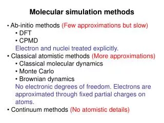
The core of the problem: • Thermal behavior is described by the differential equation of heat transfer – description is on physical level • Two different abstraction levels have to be treated • The electrical behavior of semiconductor devices is well described by compact (lumped) models The semiconductor equations (PDE-s) are replaced by analytical models (lumped/compact) – these are the device characteristics:
Possible simulation methods • Neglect thermal effects – that is the practice now in most cases: • problems remain hidden • Physical level simulation • OK for a single device but can not be used in VLSI design • Simulator coupling: • Circuit simulator that calculates dissipation values and semiconductor model parameters can be recalculated for any temperature • Thermal simulator to provide temperature distribution from the dissipation data
Possible simulation methods ANSYS SPICE TRANS-TRAN • Simulator coupling: • Problems: • Double iteration • Inside a simulator • Between the simulators • Can not treat circuits with strong thermal coupling • Dynamic electro-thermal behavior (ac, transient) improperly treated • Simultaneous solution (direct method, fully coupled) • Difficult to implement • El.-th. device models? • Efficient thermal model? • Gives correct solutions • For thermal feed-back, • Strong couplings • Dynamic behavior
Electro-thermal simulation – physical level or General driving force of carriers and Let us substitute: Furthermore: and With these substitutions we end up with: and and Let us further substitute: Differential Ohm’s law • Let us consider the flow of carriers in a piece of n-type semiconductor
Electro-thermal simulation – physical level Heat-flow equation analogous to the differential Ohm’s law • Coupled flow of charge carriers and energy: S – Seebeck coefficient Electro-thermal cross terms accounting for Seebeck- & Peltier-effect. • Let us consider the heat-flow current density– heat flux electrical conductivity– thermal conductivity potential– temperature
Electro-thermal simulation – physical level Might be important in analog IC/MEMS design Neglected in analog IC design • Seebeck-effect: Let us assume After integrating both sides: Thermo potential: proportional to the temperature difference of two locations • Peltier-effect: Let us assume Electrically pumped heat-flow
Electro-thermal simulation – physical level • Tools solving the joint system of partial differential equations (plus Poission’s eq.) are called physicaldevice simulators. • They are suitable for single devices (such as power semiconductors) but can not be used in analog IC design where there are multiples of semiconductors. (execution times, amount of data, difficult problem input)
SIMULTANEOUS SIMULATION:operation of a circuit simulatorelectro-thermal device modelsthermal model of the chip
Simultaneous simulation • Simultaneous simulation is a method that allows fast and accurateelectro-thermal CIRCUIT simulation • Requirements: • Circuit simulation engine with electro-thermal device models • Method of generating electrical model of the thermal system, suitable for circuit simulation • Efficient handling the model of the thermal subsystem during the simultaneous electro-thermal simulation
Simultaneous simulation Analogy between electrical and thermal systems is used again: dissipator / heat source current generator temperature nodal voltage (potential) temperaturedifference voltage ambient temperature electrical ground thermal resistance resistor thermal capacitance capacitor
Circuit simulation programs • The most widely known program is SPICE • Berkeley SPICE • PSPICE • other commercial versions • BUTE Dept. of Electron Devices: TRANS-TRAN (1969…2003) • Many versions for many platforms • First electro-thermal version: 1972. Now it is called SISSI • Helsinki University of Technology: APLAC • SABER, ELDO • etc.
Structure of a circuit simulator GUI Preprocessor netlist Input deck (stimuli, control cards, options) Solver (simulation engine or algorithmiccore) Library of device parameters Result files Postprocessor
The (graphical) user interface • Can be realized using the services of the actual design framework – see e.g. Cadence Opus • composer • waveform display program • Can be part of the circuit simulator system like in • PSPICE • TRANZ-TRAN (DOS, SISSI) • Microcap • etc.
The simulation engine netlist Generation of the network equation Mathematical solution algorithms Device models Library of device parameters
The simulation engine • Generation of network equations: Automatic generation of the Kirchhoff-equations • Mathematical solution algorithms: Solution of the Kirchhoff-equations • Device models: Semiconductor devices, passive components, generators, etc. The accuracy of these models determines the accuracy of the simulation.
Different types of analysis The most important types of analysis are: • Non-linear DC (determination of the operating point) • Calculation of the DC transfer characteristics (DC simulations in series) • Non-linear transient analysis – time domain analysis • Small signal AC analysis (linearization in the operating point) – frequency domain analysis • at a single frequency • Bode-plot calculation The actual mathematical solution algorithm is determined by the type of analysis in question.
The nodal solution method • The primary properties are the nodal voltages of the network (potentials with respect to the reference point – the “ground”) • Easy to implement • Semiconductor device models fit best the nodal method since most of the models supply branch currents as function of branch voltages • This is the most popular solution method • Inductivity (+transformer) and voltage generators can be described only with non-ideal models (with internal resistance) • The method is based on the nodal admittance matrix
The nodal admittance matrix n-1 n-port j+2 j+1 Ij j 2 1 0 Uj • We shall have a look how to create the admittance matrix of a linear n-port: Definite admittance matrix
The nodal admittance matrix – a) • The admittance matrix of an “empty circuit”
The nodal admittance matrix – b) v k k v +G -G +G -G Vk • The admittance matrix of a circuit containing a G conductance Ik k G Iv v Vv
The nodal admittance matrix – c) vv vk ik iv -S +S -S +S • The admittance matrix of a circuit containing a voltage controlled current source with transconductance S vk ik Ux S·Ux vv iv
The nodal admittance matrix – d) • The admittance matrix two circuits connected in parallel Yjs= Y1js+ Y2js Using rules a) .. d) the admittance matrix can be directly generated from the netlist.
Kij – the incidence matrix 0 if branch i and node j are not connected +1 if branch i starts at node j -1 if branch i ends at node j The nodal incidence matrix, Kirchhoff’s equations 3 2 3 4 Nodal currents: Ij– nodal currents Ji– branch currents N – number of branches 1 2 5 4 7 1 Branch voltages: Ur– branch voltages Vs – nodal voltages M – number of nodes 6 0 M = 4 N = 7
The general branch determines the nature of branch equations, thus, the analysis options One of the simplest branch equation is Ohm’s law General branch for linear steady-state analysis: The branch equation is: Gii– own conductance Gir– transconductance (i r) Generating the equations to be solvedfor linear DC simulation Ji Ui JGi Gii Branch current is due to the internal branch current JG and to the own branch voltage or to any other branch voltage.
The branch equation is substituted into the nodal current equation: The branch voltages are expressed from the voltage equation Generating the equations to be solvedfor linear DC simulation Ji JGi Ui Gii
We switch off external voltages – thus nodal currents will be 0: Generating the equations to be solvedfor linear DC simulation Ji JGi Ui Gir • The only unknown is the vector of the Vs nodal voltages. This is a linear equation system of M unknowns.
The general branch: This results in a non-linear equation system to be solved: This is a non-linear equation system of M unknowns which can be solved e.g. by the Newton-Raphson method. Equations to be solvedfor non-linear DC simulation Ji JGi(Ur) Ui Gir Now the JG own branch current is a (non-linear) function of any Ur branch voltage.