Digital signal processors (DSP)
370 likes | 881 Vues
Digital signal processors (DSP). Content. Digital signal processing principles (4) DSP Manufacturers Architecture of DSP Digital filters design and implementation Other types of signal processing. Introduction to DSP.

Digital signal processors (DSP)
E N D
Presentation Transcript
Content • Digital signal processing principles (4) • DSP Manufacturers • Architecture of DSP • Digital filters design and implementation • Other types of signal processing
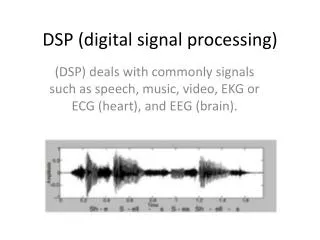
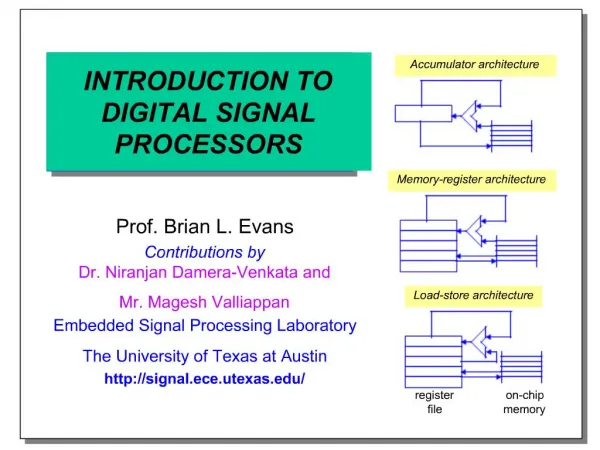
Introduction to DSP The goal of DSP is usually to measure, filter and/or compress continuous real-world analog signals. The first step is usually to convert the signal from an analog to a digital form, by sampling it using an analog-to-digital converter (ADC), which turns the analog signal into a stream of numbers. However, often, the required output signal is another analog output signal, which requires a digital-to-analog converter (DAC).
Even if this process is more complex than analog processing and has a discrete value range, • the application of computational power to digital signal processing allows for many advantages over analog processing in many applications, such as error detection and correction in transmission as well as data compression.
advantages over analog processing: • All characteristics may be 100% repeated • Easy way to change any processing algorithm • Diminishing size (power supply and other features) of device • Embedded diagnostics etc.
The main applications of DSP are audio signal processing, audio compression, digital image processing, video compression, speech processing, speech recognition, Digital communications, RADAR, SONAR, seismology and biomedicine.
Specific examples are transmission in digital mobile phones, room correction of sound in hi-fi and sound reinforcement applications, analysis and control of industrial processes, medical imaging such as CAT scans computer graphics, image manipulation, hi-fi loudspeakercrossovers and equalization, and audio effects.
Texas Instruments (TI) Analog Devices Motorola Other firms Main manufacturers
Firms Which uses DSP of TI • Xybernaut • Kodak • Nokia • 3Com • e.Digital • SonyEricsson • Hewlett Packard • Sony • Palm
С6211В: 1200 - 1336 MIPS 1,8 В 25,85 - 26,93 у.е. С6201: 1600 MIPS 1,8 В 82,70 - 99,24 у.е. С6416Т: 4800 - 8000 MIPS 1,1 - 1,2 В 114,45 - 247,36 у.е. С6411: 2400 MIPS 1,2 В 42,21 у.е. Charicteristics С6713: 1000 - 1350 MFLOPS 1,26 В 23,25 - 28, 99 у.е.
ADSP21xxcore Более детально структура ADSP приведена ниже
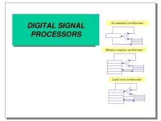
Double Harvard architecture • Two data memories and two program memories and doubled inside buses – the main features of this architecture.
Introduction to signal processing • There are two unequal types of signal processing • Linear (digital filtering) • Non-linear (all other methods)
Digital filtering • The design of digital filters is a deceptively complex topic. Although filters are easily understood and calculated, the practical challenges of their design and implementation are significant and are the subject of much advanced research. • There are two categories of digital filter: the recursive filter and the nonrecursive filter. These are often referred to as infinite impulse response (IIR) filters and finite impulse response (FIR) filters, respectively.
Digital filtering • The impulse response is the output of a system when the input is an impulse. • In this same manner, the step response is the output when the input is a step (also called an edge, and an edge response). Since the step is the integral of the impulse, the step response is the integral of the impulse response. • This provides two ways to find the step response: (1) feed a step waveform into the filter and see what comes out, or (2) integrate the impulse response.
Digital filtering • To be mathematically correct: integration is used with continuous signals, while discrete integration, i.e., a running sum, is used with discrete signals). • The frequency response can be found by taking the DFT (using the FFT algorithm) of the impulse response. • The frequency response can be plotted on a linear vertical axis, such as in (c), or on a logarithmic scale (decibels), as shown in (d).
4 types of filters • Figs. 14-8 shows how low-pass and high-pass filter kernels can be combined to form band-pass and band-reject filters. • In short, adding the filter kernels produces a band-reject filter, while convolving the filter kernels produces a band-pass filter. These are based on the way cascaded and parallel systems are be combined.
Impulse responseof digital filter • The impulse response, often denoted h[k] or hk, is a measurement of how a filter will respond to the Kronecker delta function. The impulse response is a characterization of the filter's behaviour. Digital filters are typically considered in two categories: infinite impulse response (IIR) and finite impulse response (FIR).
Difference equation • Linear form • Difference equation for IIR: • This equation shows how to compute the next output sample, y[n], in terms of the past outputs, y[n − p], the present input, x[n], and the past inputs, x[n − p].
IIR filter realization in Direct Form I • The difference equation is evaluated directly. This form is practical for small filters, but may be inefficient and impractical (numerically unstable) for complex designs
Filters classification • There are many different methods of filter design and …
Nonlinear Signal Processing • For some signal processing systems, nonlinearity is an essential component: classical examples for nonlinear systems are quantizers and pattern classifiers. • For nonlinear dynamical systems (such as oscillators, filters etc.), the conventional approach to their analysis and design has been linearization as seen e.g. in the field of adaptive filtering.
Nonlinear Signal Processing • Modulation/Demodulation • Adaptive and median filters • Image Encoding and Compression • Video Encoding and Compression • Error proof coding
TMS32LF2407 appl card • For digital spectrum 28
Next series • C2000, C3000, C4000, C5000, C6000 • TMS320 C2000 series consists of 2 families: C240x, an older 16-bit line that is no longer recommended for new development and the C28xx 32-bit line. • The newer C28xx family consists of a Delfino high-performance floating point line and a low-cost Piccolo line. The C2000 series is notable for its high performance set of on-chip control peripherals including PWM, ADC, quadrature encoder modules, and capture modules. The series also contains support for I2C, SPI, serial (SCI), CAN, watchdog, McBSP, external memory interface and GPIO.

![Global Digital Signal Processors [DSP] Market Forecast](https://cdn4.slideserve.com/1477223/marketsandmarkets-presents-dt.jpg)