Download
1 / 87
1.12k likes | 4.47k Vues
CHAPTER 28 CAMSHAFTS AND VALVE TRAINS. OBJECTIVES. After studying Chapter 28, the reader should be able to: Prepare for the ASE Engine Repair (A1) certification test content area “B” (Cylinder Head and Valve Train Diagnosis and Repair). Describe how the camshaft and valve train function.

E N D
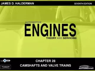
CHAPTER 28 CAMSHAFTS AND VALVE TRAINS
OBJECTIVES After studying Chapter 28, the reader should be able to: • Prepare for the ASE Engine Repair (A1) certification test content area “B” (Cylinder Head and Valve Train Diagnosis and Repair). • Describe how the camshaft and valve train function. • Discuss valve train noise and its causes. • Explain how a hydraulic lifter works. • Describe the purpose and function of variable valve timing.
Aerated Asymmetrical Bucket Cam chucking Cam follower Cam-in-block Camshaft bearings Camshaft duration Composite camshaft Double roller chain Dual overhead camshaft (DOHC) Finger follower Flat-link type Freewheeling engine Hydraulic lash adjusters (HLA) Hydraulic valve lifter Interference engine Lobe Lobe centers Lobe displacement angle (LDA) Lobe lift Lobe separation Lobe spread KEY TERMS
Morse type Oil control valve (OCV) Overhead camshaft (OHC) Overhead valve (OHV) Pump-up Ramp Roller chain type Scavenging Seat duration Silent chain type Single overhead camshaft (SOHC) Solid valve lifter Symmetrical Thrust plate Total indicator runout (TIR) Valve cam phases (VCP) Valve (camshaft) overlap Valve float Valve lash Variable valve timing (VVT) Variable valve timing and lift electronic control (VTEC) KEY TERMS
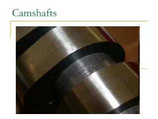
CAMSHAFT • The major function of a camshaft is to open the valves. • Camshafts have eccentric shapes called lobes that open the valve against the force of the valve springs. • The valve spring closes the valve when the camshaft rotates off of the lobe. • The camshaft lobe changes rotary motion (camshaft) to linear motion (valves). • Cam shape or contour is the major factor in determining the operating characteristics of the engine.
FIGURE 28–1 This high-performance camshaft has a lobe that opens the valve quickly and keeps it open for a long time. CAMSHAFT • The camshaft is driven by: • Timing gears • Timing chains • Timing belts
FIGURE 28–2 In many engines, the camshaft drives the distributor and the oil pump through a shaft from the end of the distributor. CAMSHAFT
FIGURE 28–3 The camshaft rides on bearings inside the engine block above the crankshaft on a typical cam-in-block engine. CAMSHAFT • There are two basic areas where the camshaft can be located in an engine. • In the engine block • Overhead
FIGURE 28–4 Parts of a cam and camshaft terms (nomenclature). CAMSHAFT DESIGN • CONSTRUCTION • CAMSHAFT BEARING JOURNALS • HARDNESS • CAMSHAFT LUBRICATION • FUEL PUMP ECCENTRICS
FIGURE 28–5 A composite camshaft is lightweight and yet flexible, because the hollow tube can absorb twisting forces and the lobes are hard enough to withstand the forces involved in opening valves. CAMSHAFT DESIGN
FIGURE 28–6 Worn camshaft with two lobes worn to the point of being almost round. CAMSHAFT DESIGN
FIGURE 28–7 The fuel pump rocker arm rides on the camshaft eccentric. CAMSHAFT DESIGN
FIGURE 28–8 A timing chain hydraulic tensioner. CAMSHAFT DRIVES • The crankshaft drives the camshaft with one of the following: • Timing gears • Sprockets and chains • Sprockets and timing belts
FIGURE 28–9 The larger camshaft gear is usually made from fiber and given a helical cut to help reduce noise. By making the camshaft gear twice as large as the crankshaft gear, the camshaft rotates one revolution for every two of the crankshaft. CAMSHAFT DRIVES • CAMSHAFT CHAIN DRIVES • CAMSHAFT BELT DRIVES
FIGURE 28–11 The industry standard for when to replace a timing chain and gears is when 1/2 in. (13 mm) or more of slack is measured in the chain. However, it is best to replace the timing chain and gear anytime the camshaft is replaced or the engine is disassembled for repair or overhaul. FIGURE 28–10 A replacement silent chain and sprockets. The original camshaft sprocket was aluminum with nylon teeth to help control noise. This replacement set will not be noticeably louder than the original and should give the owner many thousands of miles of useful service. CAMSHAFT DRIVES
FIGURE 28–12 A replacement high-performance double roller chain. Even though a bit noisier than a flat-link chain, a roller chain does not stretch as much and will therefore be able to maintain accurate valve timing for a long time. FIGURE 28–13 This dual overhead camshaft (DOHC) engine uses one chain from the crankshaft to the intake cam and a secondary chain to rotate the exhaust camshaft. CAMSHAFT DRIVES
FIGURE 28–15 This timing belt broke because an oil leak from one of the camshaft seals caused oil to get into and weaken the belt. Most experts recommend replacing all engine seals in the front of the engine anytime a timing belt is replaced. If the timing belt travels over the water pump, the water pump should also be replaced as a precaution. FIGURE 28–14 A timing belt failed when the teeth were sheared off. This belt failed at 88,000 miles because the owner failed to replace it at the recommended interval of 60,000 miles. CAMSHAFT DRIVES
FIGURE 28–16 Many engines are of the interference design. If the timing belt (or chain) breaks, the piston still moves up and down in the cylinder while the valves remain stationary. With a freewheeling design, nothing is damaged, but in an interference engine, the valves are often bent. FIGURE 28–17 A head from a Mercedes showing bent valves when the timing chain stretched and skipped over the crankshaft sprocket. When this happened, the piston kept moving and bent the valves. CAMSHAFT DRIVES
FIGURE 28–18 The slight angle and the curve on the bottom of a flat bottom lifter cause the lifter and the pushrod to rotate during normal operation. CAMSHAFT MOVEMENT • REASONS CAMSHAFTS MOVE • WHY FLAT-BOTTOM LIFTERS ROTATE • CAMSHAFT LOBE LIFT
FIGURE 28–19 The lobe lift is the amount the cam lobe lifts the lifter. The blue circle is called the base circle. Because the rocker arm adds to this amount, the entire valve train has to be considered when selecting a camshaft that has the desired lift and duration. CAMSHAFT MOVEMENT
FIGURE 28–20 The ramps on the cam lobe allow the valves to be opened and closed quickly yet under control to avoid damaging valve train components, especially at high engine speeds. CAMSHAFT MOVEMENT
Best to Warn the Customer • A technician replaced a timing chain and gears on a high mileage Chevrolet V-8. The repair was accomplished correctly, yet after starting, the engine burned an excessive amount of oil. Before the timing chain replacement, oil consumption was minimal. The replacement timing chain restored proper operation of the engine by restoring the proper cam and valve timing which increased engine vacuum. Increased vacuum can draw oil from the crankcase past worn piston rings and through worn valve guides during the intake stroke. Similar increased oil consumption problems occur if a valve job is performed on a high-mileage engine with worn piston rings and/or cylinders. • To satisfy the owner of the vehicle, the technicians had to disassemble and refinish the cylinders and replace the piston rings. Therefore, all technicians should warn customers that increased oil usage might result from almost any engine repair to a high-mileage engine.
ROCKER ARMS • A rocker arm reverses the upward movement of the pushrod to produce a downward movement on the tip of the valve. • Engine designers make good use of the rocker arm. • It is designed to reduce the travel of the cam follower or lifter and pushrod while maintaining the required valve lift. • This is done by using a rocker arm ratio usually of 1.5:1.
FIGURE 28–21 A 1.5:1 ratio rocker arm means that dimension A is 1.5 times the length of dimension B. Therefore, if the pushrod is moved up 0.4 in. by the camshaft lobe, the valve will be pushed down (opened) 0.4 in. x 1.5, or 0.6 in. ROCKER ARMS • SHAFT-MOUNTED ROCKER ARMS • STUD-MOUNTED ROCKER ARMS • PEDESTAL-MOUNTED ROCKER ARMS
FIGURE 28–22 A high-performance aluminum roller rocker arm. Both the pivot and the tip that contacts the stem of the valve are equipped with rollers to help reduce friction for more power and better fuel economy. ROCKER ARMS
FIGURE 28–23 Some engines today use rocker shafts to support rocker arms such as the V-6 engine with a single overhead camshaft located in the center of the cylinder head. ROCKER ARMS
FIGURE 28–24 A typical stud-mounted rocker arm. FIGURE 28–25 Pushrod guide plates are bolted to the head and help stabilize the valve train, especially at high engine speeds. ROCKER ARMS
Are the Valves Adjustable? • If the stud has the same diameter for its whole length, the rockers are adjustable and the nut will be the “interference” type (lock-type nut). If the stud has a shoulder of a different diameter, the rockers are nonadjustable and the nut will not have interference threads.
FIGURE 28–26 A pedestal-type rocker arm design that used one bolt for each rocker arm and is nonadjustable. If valve lash needs to be adjusted, different length pushrod(s) must be used. ROCKER ARMS
Rocker Arm Shafts Can Cause Sticking Valves • As oil oxidizes, it forms a varnish. Varnish buildup is particularly common on hot upper portions of the engine, such as rocker arm shafts. The varnish restricts clean oil from getting into and lubricating the rocker arms. The cam lobe can easily force the valves open, but the valve springs often do not exert enough force to fully close the valves. The result is an engine miss, which may be intermittent. Worn valve guides and/or weak valve springs can also cause occasional rough idle, uneven running, or an engine misfire.
FIGURE 28–27 Overhead valve engines are also known as pushrod engines because of the long pushrod that extends from the lifter to the rocker arm. PUSHRODS • Pushrods transfer the lifting motion of the valve train from the cam lobe and lifters to the rocker arms.
FIGURE 28–28 When the timing chain broke, the valves stopped moving up and down but the pistons kept moving and hit the valves causing the pushrods to bend. PUSHRODS
Hollow Pushrod Dirt • Many engine rebuilders and remanufacturers do not reuse old hollow pushrods. Dirt, carbon, and other debris are difficult to thoroughly clean from inside a hollow pushrod. When an engine is run with used pushrods, the trapped particles can be dislodged and ruin new bearings and other new engine parts. Therefore, for best results, consider purchasing new hollow pushrods instead of trying to clean and reuse the originals.
The Scratch Test • All pushrods used with guide plates must be hardened on the sides and on the tips. To easily determine if a pushrod is hardened, simply use a sharp pocketknife to scrape the wall of the pushrod. A heat-treated pushrod will not scratch.
FIGURE 28–29 Hardened pushrods should be used in any engine that uses pushrod guides (plates). To determine if the pushrod is hardened, simply try to scratch the side of the pushrod with a pocketknife. The Scratch Test
OVERHEAD CAMSHAFT VALVE TRAINS • Overhead camshaft engines use several different types of valve opening designs. • 1. One type opens the valves directly with a bucket. • 2. The second type uses a cam follower, also called a finger follower, that provides an opening ratio similar to that of a rocker arm. • 3. A third type moves the rocker arm directly through a hydraulic lifter. • 4. In the fourth design, some newer engines have the hydraulic adjustment in the rocker arm and are commonly called hydraulic lash adjusters (HLA).
FIGURE 28–30 Hydraulic lifters may be built into buckettype lifters on some overhead camshaft engines. FIGURE 28–31 The use of cam followers allows the use of hydraulic lifters with an overhead camshaft design. OVERHEAD CAMSHAFT VALVE TRAINS
FIGURE 28–32 Hydraulic lash adjusters (HLA) are built into the rocker arm on some OHC engines. Sometimes hydraulic lash adjusters may not bleed down properly if the wrong viscosity (SAE rating) oil is used. OVERHEAD CAMSHAFT VALVE TRAINS
CAMSHAFT SPECIFICATIONS • DURATION • VALVE OVERLAP • CALCULATING VALVE OVERLAP • LOBE CENTERS • EFFECTS OF LOBE SEPARATION ON VALVE OPERATION • CAM TIMING SPECIFICATIONS • CAM TIMING CHART
FIGURE 28–33 Graphic representation of a typical camshaft showing the relationship between the intake and exhaust valves. The shaded area represents the overlap period of 100 degrees. CAMSHAFT SPECIFICATIONS
FIGURE 28–34 As the lobe center angle decreases, the overlap increases, with no other changes in the lobe profile lift and duration. CAMSHAFT SPECIFICATIONS
FIGURE 28–35 Typical cam timing diagram. CAMSHAFT SPECIFICATIONS
FIGURE 28–36 Typical high-performance camshaft specifications on a straight-line graph. Intake valve duration = 39 + 180 + 71 = 290 degrees. Exhaust valve duration = 7 + 180 + 47 = 234 degrees. Because intake and exhaust valve specifications are different, the camshaft grind is called asymmetrical. CAMSHAFT SPECIFICATIONS
FIGURE 28–37 Typical camshaft valve timing diagram with the same specifications as those shown in Figure 28–36. CAMSHAFT SPECIFICATIONS
LIFTERS OR TAPPETS • Valve lifters or tappets follow the contour or shape of the camshaft lobe. • This arrangement changes the rotary cam motion to a reciprocating motion in the valve train. • Older-style lifters have a relatively flat surface that slides on the cam. • VALVE LASH • SOLID LIFTERS • HYDRAULIC LIFTERS
FIGURE 28–38 Older engines used flat-bottom lifters, whereas all engines since the 1990s use roller lifters. LIFTERS OR TAPPETS
FIGURE 28–39 All roller lifters must use some method to keep the lifter straight and not rotating. LIFTERS OR TAPPETS
FIGURE 28–40 A cutaway of a flat-bottom solid lifter. Because this type of lifter contains a retaining ring and oil holes, it is sometimes confused with a hydraulic lifter that also contains additional parts. The holes in this lifter are designed to supply oil to the rocker arms through a hollow pushrod. LIFTERS OR TAPPETS
FIGURE 28–41 An exploded view of a hydraulic roller lifter. LIFTERS OR TAPPETS