Download
1 / 38
570 likes | 1.65k Vues
ME 350 – Lecture 10 – Chapter 13. SHAPING PROCESSES FOR PLASTICS Properties of Polymer Melts Injection Molding Extrusion Extrudate Production Other Molding Processes Thermoforming Casting Polymer Foam Processing Product Design Considerations. Polymer Melt - Viscosity.

E N D
ME 350 – Lecture 10 – Chapter 13 SHAPING PROCESSES FOR PLASTICS • Properties of Polymer Melts • Injection Molding • Extrusion • Extrudate Production • Other Molding Processes • Thermoforming • Casting • Polymer Foam Processing • Product Design Considerations
Polymer Melt - Viscosity Shear rate and viscosity: thinner at higher shear rates Temperature & viscosity: thinner at higher temperature
Die Swell, aka: Viscoelasticity Extruded polymer "remembers" its previous shape when in the larger cross section of the extruder, tries to return to it after leaving the die orifice Swell ratio: rs = Dx / Dd Die swell, a manifestation of viscoelasticity in polymer melts.
Injection Molding Polymer is heated to a highly plastic state and forced to flow under high pressure into a mold cavity where it solidifies and the molding is then removed. • Produces discrete components almost always to net shape or near net shape • Typical cycle time 1 to 30 sec • Mold may contain multiple cavities, so multiple moldings are produced each cycle • Some thermosets and elastomers are injection molded, but equipment and operating parameters must be modified to avoid: premature cross‑linking
Injection Molding Machine Two principal components: • Injection unit (operates similar to an extruder) • Melts and delivers polymer melt (plunger for injection) • Clamping unit • Opens and closes mold each injection cycle
1. Mold Closes 2. Inject Plastic 3. Cooling Time 4. Mold Opens
Cooling time: Ballman / Shusman model tcooling = • (Tdeflect – Tmold) 4(Tmelt – Tmold) - Pmax_thickness2 x ln 2ThDiffusivity Injection Molding Time/Cost Model Injection time: machine and material manufacturers data tinjection = {(Ncav x Vcav) + Vrunner} / Rmax_injection x Matfactor Ejection time: from machine manufacturers data tejection = f(tdry_cycle) Cycle Time: tcycle = tinjection + tcooling + tejection Direct Mc/Overhead Cost: CM/c_overhead = Mcrate x tcycle / Ncav Labor Cost: Clabor = Labratio x Labrate x tcycle / Ncav
The Mold (Tooling)
Two‑Plate Mold • Cavity – slightly oversized to allow for shrinkage • Distribution channel • Sprue - leads from nozzle into mold • Runners - lead from sprue to cavity (or cavities) • Gates - constricts flow to: decrease viscosity • Ejection system – pins built into moving half of mold • Cooling system – typically water • Air vents – at end of flow path
Three‑Plate Mold Uses three plates to separate parts from sprue and runner when mold opens (Fig 13.24) • Advantages over two-plate mold: • As mold opens, runner and parts disconnect and drop into two separate containers under mold • Allows automatic operation of molding machine • Allows material to be injected at the mold base or middle, rather than side injection, which a two-plate mold must do.
Hot‑Runner Mold • Heaters are located around the runner channels which eliminates solidification of the: sprue and runner • This type of mold improves mold flow as material is heated right up to when in enters the cavity.
Shrinkage • Polymers have high thermal expansion coefficients, so significant shrinkage occurs during solidification • Typical shrinkage values: PlasticShrinkage, mm/mm (in/in) Nylon‑6,6 0.020 Polyethylene 0.025 Polystyrene 0.004 PVC 0.005 • Dimensions of mold cavity must be larger than specified part dimensions: Dc= Dp + DpS + DpS2 where Dc = dimension of cavity; Dp = molded part dimension, and S = shrinkage value and the third term on right hand side corrects for shrinkage in the shrinkage
Shrinkage Factors • Fillers in the plastic tend to: reduce shrinkage • Injection pressure – higher pressures in the mold cavity tend to: reduce shrinkage • Compaction time – longer time tends to: reduce shrinkage • Molding temperature - higher temperatures lower polymer melt viscosity, which tends to: reduce shrinkage
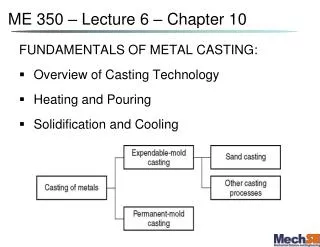
Extrusion Heated plastic is forced to flow through a die orifice to provide a long continuous product (tube, sheet, etc.) whose cross‑sectional shape is determined by the die orifice. The extrudate is then cut into desired lengths. Three zones in an extruder: feed, compression, & metering.
Die End of Extruder • Progress of polymer melt through barrel leads ultimately to the die zone • Before the die, the melt passes through a series of wire meshes supported by a stiff plate containing small axial holes called a: screen pack • Functions: • Filter(remove contaminants and any hard lumps) • Build pressurein the metering section • Straighten flow- remove "memory" of circular motion from screw
Melt Flow in Extruder • Archimedian screw forces polymer melt toward die • Principal transport mechanism is Qd, resulting from friction between the viscous liquid and the rotating screw: drag flow • Compressing the polymer melt through the die creates a back pressure that reduces drag flow transport, Qb called: back pressure flow • Resulting flow in extruder is: Qx = Qd – Qb
Extruder Screw Melt Flow (pg 264-265) Qd = 0.5 π2 D2 N dc sinA cosA Where, D – flight screw diameter N – screw rotational speed dc – screw channel depth A – flight angle Qb ≈ Where, p – head pressure (die) η – melt viscosity L – length of the barrel Assumes leakage flow is negligible Qx = Qd - Qb Drag Flow Qd→ Back Pressure Flow Qb ← Flight angle ‘A’? tan A = p / πD
Extruder Screw Melt Flow (pg 266) • Boundary Conditions: • With no back pressure • Qx = Qmax = Qd • 2) With no flow • Qx = 0 = Qd – Qb, • pmax = Extruder characteristic Qx = Qmax – (Qmax/pmax)p Qmax Die characteristic Qx = Ksp Melt flow Ks = (for round opening) Dd – effective die opening Ld – effective die opening length Head pressure pmax Intersection (Qx,p) known as the operating point
Thermoplastic Foam Injection Molding Molding of thermoplastic parts that possess dense outer skin surrounding lightweight foam center • Part has high stiffness‑to‑weight ratio suited to structural applications • Produced either by introducing a gas into molten plastic in injection unit or by mixing a gas‑producing ingredient with starting pellets • A small amount of melt is injected into mold cavity, where it expands to fill cavity • Foam in contact with cold mold surface collapses to form dense skin, while core retains cellular structure
Injection Molding of Thermosets • Temperatures in the injector are generally: lower • The barrel length of the injection unit is generally: shorter • Melt is injected into a heated mold, where cross‑linking occurs to cure the plastic • The most time‑consuming step in the cycle: curing in the mold
Compression Molding • A widely used molding process for thermosets • Also used for rubber tires and polymer composites • Molding compound available in several forms: powders or pellets, liquid, or preform • Amount of charge must be precisely controlled (1) charge is loaded, (2) and (3) charge is compressed and cured, and (4) part is ejected and removed.
Molds for Compression Molding • Simpler than injection molds • As opposed to injection molding, there is no: sprue and runner system • Limited to simpler part geometries due to lower flow capabilities of TS materials • Mold must be heated, usually by electric resistance, steam, etc • Typical molding materials: phenolics, melamine, epoxies, urethanes, and elastomers • Typical compression-molded products: • Electric plugs, sockets, and housings; pot handles, and dinnerware plates
Transfer Molding TS charge is loaded into a heated chamber; pressure is applied to force the soft polymer into the heated mold. • Pot transfer molding: charge is injected from a "pot" through a vertical sprue channel into cavity • Plunger transfer molding: plunger injects charge from a heated well through channels into cavity
Compression vs. Transfer Molding • In both processes, scrap is produced each cycle as leftover material, called the: cull • The TS scrap cannot be recovered • Transfer molding is capable of molding more intricate part shapes than compression molding but not as intricate as injection molding • Transfer molding lends itself to molding with inserts, in which a metal or ceramic insert is placed into cavity prior to injection, and the plastic bonds to insert during molding
Blow Molding • Molding process in which air pressure is used to inflate soft plastic into a mold cavity • Material limited to: thermoplastics • Accomplished in two steps: • Fabrication of a starting tube, called a: parison • Inflation of the tube to desired final shape • Two methods: • Extrusion blow molding • Injection blow molding
Extrusion Blow Molding (1) extrusion of parison; (2) parison is pinched at the top and sealed at the bottom around a metal blow pin as the two halves of the mold come together; (3) the parison is inflated; and (4) mold is opened to remove the solidified part.
Injection Blow Molding (1) parison is injection molded around a blowing rod; (2) injection mold is opened and parison is transferred to a blow mold; (3) parison is inflated; and (4) blow mold is opened and product removed.
Vacuum Thermoforming • Starting material:thermoplastic sheetor film • To soften, heat is supplied by radiant electric heaters located on one or both sides Products: bathtubs, contoured skylights, door liners for refrigerators, boat hulls, shower stalls, advertising displays and signs, etc.
Polymer Casting Pouring liquid resin into a mold, using gravity to fill cavity, where polymer hardens • Both thermoplastics and thermosets are cast • Thermoplastics: acrylics, polystyrene, polyamides (nylons) and PVC • Thermosetting polymers: polyurethane, unsaturated polyesters, phenolics, and epoxies • Simpler mold • Suited to low quantities
Polymer Foams • A polymer‑and‑gas mixture, with gas added by: • physical mixing or injection (air, nitrogen, CO2) • chemical blowing agent that decomposes at elevated temperatures • Two types: • closed cell (a) • open cell (b) • Product methods: • make the beads first, then feed the beads into a cavity to be fused together (e.g. styrofoam cups) • injection mold using a chemical blowing agent • extrude sheets (least expensive method)
Product Design Guidelines: General • Strength and stiffness • Plastics are not as strong or stiff as metals • Avoid applications where high stresses will be encountered • Creep resistance is also a limitation • Strength‑to‑weight ratios for some plastics are competitive with metals in certain applications
Product Design Guidelines: General • Impact Resistance • Capacity of plastics to absorb impact is generally good; plastics compare favorably with most metals • Service temperatures • Limited relative to metals and ceramics • Thermal expansion • Dimensional changes due to temperature changes much more significant than for metals
Product Design Guidelines: General • Many plastics are subject to degradation from sunlight and other forms of radiation • Some plastics degrade in oxygen and ozone atmospheres • Plastics are soluble in many common solvents • Plastics are resistant to conventional corrosion mechanisms that afflict many metals