Introduction to Solo Forest
600 likes | 774 Vues
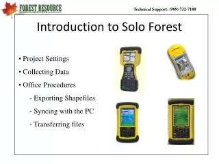
Introduction to Solo Forest. Project Settings Collecting Data Office Procedures - Exporting Shapefiles - Syncing with the PC - Transferring files. Opening Solo Forest. To open Solo Forest , select Start > Solo Forest .

Introduction to Solo Forest
E N D
Presentation Transcript
Introduction to Solo Forest • Project Settings • Collecting Data • Office Procedures - Exporting Shapefiles - Syncing with the PC - Transferring files
Opening Solo Forest To open Solo Forest , select Start > Solo Forest. If you programmed Solo Forest as one of your Button shortcuts, you may also open it by selecting the upper right button on the Recon X or Ranger X.
Creating a UDF Project After executing the Solo shortcut, you will be fad with this screen: Opens the last project that was used Opens a project that has been previously created but was not the last used Begins a completely new Solo Forest project Exits out of Solo Forest
No GPS Data Screen If you do not have GPS going when you open the Solo Forest program, Solo will let you know that it does not see any GPS data by displaying the following screen. It is not an error. It is simply a fact that it is not receiving any GPS data. When this occurs, simply select the Do not repeat this message again this session box and it will not harass you again during the current session.
Naming the Project When you begin a new project, Solo takes you to one of the following default Solo folder locations: Pocket PC – Built-in Storage\My Documents\Solo Windows Mobile – My Documents\Solo To begin a new project, we must first name it. In this example, we will use the name Training. The default name that appears is a number string that represents the year, the month, the day, and the time. To type training, simply double click the numbers in the Name: cell and use your keyboard to enter “Training”. Select OK at the top right or bottom left and you will go to the Settings Options in Solo Forest. 99% of the time you will not need to modify any settings, but you do need to understand them.
Info Tab Solo Forest Settings The Info Tab gives the Solo Forest Version Information along with the Project Name and the Directory it is being stored. It also gives the number of features that has been collected. Sin this is a new project, there is no feature or point data.
Solo Forest Settings General Tab The General Tab allows you to determine how you want to see your data in the field. Most people like to see Latitude-Longitude and Feet. After you have finished mapping your features you can export your shapefiles as Lat-Long (i.e.. Geographic), or, if you set the Position display to Northing-Easting and your Distance unit as Meters, then Solo will export your shapefiles in the Coordinate system, Datum, and Zone that are set up on the Zone tab (for example UTM, NAD83, Zone 16). ArcGIS can handle either method, but fGIS has to have the GPS data match the basemap data.
Solo Forest Settings Zone Tab The Zone Tab allows us to configure the Projection Settings which include the Coordinate System, Horizontal Datum, and Zone. If you plan on using Base Maps/Images in the field, you will want to set this to match those.
Solo Forest Settings Logging Tab The Logging Tab gives us an opportunity to set some parameters around how we want to collect data. We can determine what we want to happen when we begin collecting data by configuring the “When a point is created…” box. These are the recommended settings.
Solo Forest Settings Signal Tab The Signal Tab is where we set our parameters for maximum allowable HDOP or PDOP. We can also select the minimum number of observations to be collected during a static point. You may also want to choose whether or not you want to accept data if it is not being differentially corrected RealTime (DGPS). We recommend not checking this box unless you are doing a mapping project that requires DGPS data only. Please read through these options before continuing.
Solo Forest Settings Files Tab The Files Tab is where we can set up the folders where we want our data stored and backed up. You will have one of the following locations depending upon your operating system: Pocket PC – Built-in Storage\My Documents \Solo Windows Mobile – My Documents\Solo Do not change or modify these folders. Also, we can select the Feature File we wish to use for the project and we can load or clear a waypoint or grid file.
Solo Forest Settings Receiver Tab The Receiver Tab allows us to choose the type of GPS receiver with which we will be collecting data. Garmin 17-N applies to all Garmin receivers. COM 1 applies to any receiver that will be plugged in the 9 pin Serial Port on the bottom of the handheld. If you are using a Bluetooth GPS receiver, you will usually select COM 8. If you have all of the GPS peripherals connected and are not receiving a signal, make sure the “GPS receiver not used” box is not selected.
Solo Forest Settings Laser Tab Be sure and check the Laser not used – Manual Entry box on the Laser tab because we will need that set up correctly when we use the Log by Laser technique under the Advanced GPS section. You can now select OK in either the top right or bottom left corners.
Solo Forest Main Screen • Map Area • Data Collection Toolbar • Zoom Toolbar • Menus 4 Parts
Solo Forest Menus File Menu New = Start a new project Open = Open an existing project Settings = Settings Feature Codes = Edit Feature Codes More > Export = Export mapped features as shapefiles
Solo Forest Menus Edit Menu Delete = Delete a node or feature Move = Move a node Copy to UDF Feature = used in Freehand Redlining Logged Data > Logged Features = a way to see all logged data Find Feature = a way to search through shapefile attributes
Solo Forest Menus View Menu Zoom Options = ignore and use the Zoom Toolbar Map Layers = Where to go to add a basemap layer Display Options = where to go to change Toolbar icons, etc. Satellite Sky Plot = shows satellite status
Solo Forest Menus Changing Toolbar Icons To change the icons on the Toolbars, go to View > Display Options > Toolbars > Toolbar Buttons… and set the Zoom and Mode Toolbars to what you like.
Solo Forest Menus Log Menu Log a Point = Log Static Log at… = Allows node to node joining of 2 features Log by Interval > Log by Interval = Log Dynamic Sticky Log = Heads up digitizing
Solo Forest Menus Tool Menu Navigate = Navigate GPS Configure = Way to restart GPS or reconnect Bluetooth Generate Grid = Grid Generator Buffer Feature = Create buffers Polygons > Split/Merge = Merge or split polygons More > RTI = Initialize RTI script
Solo Forest Toolbars Zoom Toolbar Everything Follow GPS Logged Data Refresh In Out Window Previous
Solo Forest Toolbars Zoom Toolbar: Follow GPS Icon Note: If you select this icon, then the screen will move as you move. If this icon is unselected, the screen will not move as you do and you can walk off the screen as you move around or collect data. This icon is especially important to understand when you want to select a dynamic area to check acres or when you have a basemap loaded and want to zoom into an area of the basemap that is not where you are currently located. If the Follow GPS icon is selected, you will not be able to zoom in to that selection because you have told Solo Forest to keep you on the screen at all times. Uncheck this box and then zoom in again. You can also access this setting from the Menu box on the Log by Interval screen.
Solo Forest Toolbars Mode Toolbar: 2 Drop Lists The first Drop List allows us to select which method we want to log with. Most of the time we will Log with GPS Location, but sometimes we may want to log manually or use Log with Laser to enter property descriptions (line lengths and azimuths).
Solo Forest Toolbars Mode Toolbar: 2 Dropdown Lists The second Dropdown List allows us to select what we want to do with our Stylus. Most of the time we will select Stylus Selects Whole Feature, but sometimes we will want to select something else. Manual X,Y will give the coordinates of the point at which the stylus touches the screen Basemap Feature selects the Basemap Layer/Image that has been loaded, if any Whole Feature will allow you to click anywhere on the feature and select it Deletes Multiple Points will allow you select individual nodes and delete all of them at once by going to Edit > Delete Logged Data selects the feature data that has been collected Freehand Redlining allows the user to use the Freehand Redlining option Edits Basemap Feature allows the user to edit spatial and database info about the basemap
Solo Forest Toolbars Mode Toolbar: Shortcut Icons Export Shapefile Navigate Log Static Measure Create Grid Log Dynamic
Logging a Static Feature Step #1 – Single Flag We will begin collecting a static point by going to a corner and pressing the Single Flag button.
Logging a Static Feature Step # 2 – Select Feature We can now select the type of feature we wish to map. In this case we choose Timber_Stand. We will log a static point, but the overall feature will be an area feature. Note that we are selecting this off of the All Tab. Be sure and stay out of the Rent Tab. The In Progress Tab will be discussed later. You can select OK or Double click the feature. Also make sure you are standing with your antenna over the static location you want to collect because the OK button is the “trigger” to begin collecting the observations for static point averaging.
Logging a Static Feature Step #3 - Attributes After selecting our feature, the following screen will appear. This screen allows us to enter attribute information about the feature on the Attributes Tab. Next you want to select the GPS Status Tab.
Logging a Static Feature Step #4 – Check Deviation and Log Now The GPS Status Tab gives you the ability to view the number of points and the static spread or deviation of the observations between them at 1 SD. This allows you to judge the integrity of the static point as you collect the data. If you do not like the “spread” and wish to reject the point, press the small X button. On you have collected 25-30 points with a acceptable deviation (maybe < 5 feet), press the Log Now button. This will average all of the collected points together to make 1 point.
Logging a Static Feature The Property Corner is now represented on the screen. Remember, there will always be a blue diamond around the last point logged. Step # 5 – Single Flag again To add another corner to this Timber Stand Area Feature, we need to walk to that corner and then select Single Flag again.
Logging a Static Feature Step #6 – In Progress The next screen you see is basically asking, “What do you want to do?” And the answer is, “Add another Static Point to the Timber Stand in progress!!” If you wanted to begin a new feature, you would go the All tab and select a new feature off of the Feature List. Sin the correct Timber_Stand feature is already selected, click OK.
Logging a Static Feature Step # 7 – Check Deviation and Log Now Log 30 more seconds of data and check the deviation. If it is OK, press Log Now.
Logging a Static Feature The second Static point has now been added to the Timber Stand area feature.
Logging a Dynamic Feature Step #1 – Flag with a Stopwatch To add a Dynamic line to the Timber Stand feature already started, or if you want to begin a new Dynamic feature, select the Flag with a Stopwatch icon.
Logging a Dynamic Feature Step #2 – In Progress The next screen you see is asking, “What do you want to do?” And the answer is, “Add a Dynamic Line to the Timber Stand in progress!!” If you wanted to begin a new feature, you would go the All tab and select a new feature off of the Feature List. Sin the correct Timber_Stand feature is already selected, click OK.
Logging a Dynamic Feature Step #4 – Select OK at the Attribute screen.
Logging a Dynamic Feature Step #5 – Select Time or Distance and then Start In the Log by Interval screen, you can choose to log by Time or Distance. Use a 1 second interval if you are moving fast and 5-8 if you are moving slow because it is thick. Use Log by Distance if you are stopping frequently to paint a line or tie flagging. Note the Start and Pause Buttons. When you are ready to start, press Start.
Logging a Dynamic Feature Step #6 – Pause and Close Pay attention as you traverse the rest of the area feature. Be sure and turn up your handheld volume by selecting the little speaker at the top of the page because Solo Forest should beep at you letting you know that nodes are being logged. Select Pause when you want to take a break or have finished the dynamic feature. Select Close to return to the Main Screen.
Editing Data in Solo Forest OR To edit data in the field, double tap on the point/feature you wish to edit. Here, you can delete, edit position information, and/or re-order the point. If you wish to delete or edit the entire feature, make sure the feature tab is selected. Or you can simply select the feature or node and then press Edit > Delete and Yes.
Viewing Acres In-The-Field To view the acres and circumference of an area feature (or the length of a line feature), set your Stylus to Selects Whole Feature, and then simply click anywhere on that feature.
Measure Tool To measure distance in the field, simply press the Tape Measure icon and click on the screen. You will see the individual line lengths, the total line length, and the area of the polygon that you created. What your Stylus is set to affects how this tool works. To clear the measurements, simply select the Measure Tool again.
Office Procedures • Exporting Shapefiles on the handheld • Syncing the handheld with the computer • Transferring the Shapefiles to the computer
A. Exporting ShapefilesWhy do you have to do this? So far you have mapped GPS features in a UDF file. To get these features in a format that your GIS can use, you need to export them as Shapefiles. ArcGIS Users have the option of exporting their features in a Geographic (Lat-Long) or Projected (UTM) coordinate system. This is possible because ArcGIS can recognize both and reproject your data on the fly to make it line up with your basemaps. For any other GIS (like fGIS), however, you must export your mapped features in the same coordinate system, datum, and zone as your basemap. Regardless, it is probably best to go ahead and export your shapefiles to match your basemap files whatever they may be. Solo Forest allows you to set the Export projection in the Export dialogue before you create the shapefiles. Here is how that works.
Exporting Shapefiles Step #1 – Go to the Export Dialogue Select the Export Shapefile Icon or go to File > More >Export.
Exporting Shapefiles Step #2 – Settings You can select the features you want to export. Note: Solo Forest ver. 4.0.5 allows you set the Export Settings one time and they are persistent or will not change until you change them. To set the Export Projection select Options. Make sure ArcView Shapefile is selected here.
Exporting ShapefilesStep #3 – Make Project Settings match your Basemaps Next, select Projections and then change the Position Display to Northing Easting and make the Distance unit be Meters. When you select Northing-Easting, Solo Forest looks at the Zone Tab and uses whatever is described there for the shapefiles. Example: UTM, NAD83, Zone 16
Exporting Shapefiles Step #4 – Output Directory By default, the Export folder in which your shapefiles will be created is one of the following: PocketPC2003 = Built-in Storage\My Documents\Solo|Export Windows Mobile = My Documents\Solo \Export You can set it temporarily to something else, but it will default back to that the next time you open Solo.
Exporting ShapefilesStep #5 – Name the Shapefiles or Use Feature Names After you make sure the Project settings are correct and choose the Output Directory, you need to decide if you want to name your shapefiles or simply use the default Feature name + “000” (ex. Timber_Stand000). If you want to name them as they are created, select Prompt for filenames.
Exporting ShapefilesStep #6 – Select Export The last step is to Select Export. If you selected Prompt for Filename , you can then enter the new name here. Note: you will have one shapefile for every different feature you chose from your feature list. After you have named all of the shapefiles, it will tell you that that they have been created in the My Documents\Export Folder. Close that screen and go to Step B.
B. Syncing with Your PCStep #1 – Install Microsoft Activesync Microsoft Activesync is a free program that allows a handheld device to be synchronized with a computer. If you are using a computer that does not have Microsoft ActiveSync installed (i.e. look at All Programs under the start menu), then you will need to install it from your LandMark Customer thumbdrive, or download and install it from our website (http://www.landmarksystems.com/support/microsoftactivesync.htm).