Download
1 / 122
1.38k likes | 1.79k Vues
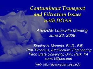
Understanding and Designing Dedicated Outdoor Air Systems (DOAS). Short Course. Stanley A. Mumma, Ph.D., P.E. Prof. Emeritus, Architectural Engineering Penn State University, Univ. Park, PA sam11@psu.edu. Web: http:// doas-radiant.psu.edu. Presentation Outline.

E N D
Understanding and Designing Dedicated Outdoor Air Systems (DOAS) Short Course Stanley A. Mumma, Ph.D., P.E. Prof. Emeritus, Architectural Engineering Penn State University, Univ. Park, PA sam11@psu.edu Web: http://doas-radiant.psu.edu
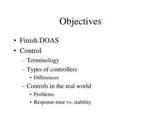
Presentation Outline • Quick review of current leading building HVAC system issues • Define DOAS • Explain terminal equipment choices and issues • Describe DOAS equipment choices and psychrometrics • Provide a DOAS design example • 30% surplus OA, why and does it use more energy? • Explain relevance of DOE and ASHRAE Research findings • Describe field applications • Conclusions
Key Presentation Points Problems with common VAV systems DOAS defined DOAS Issues Parallel sensible terminal equipment choices Total Energy Recovery issues and control Part 1:
Key Presentation Points Impact of building pressurization on DOAS Impact of 30% surplus OA on DOAS Estimating OA load—it’s not the coil load DOE Report: DOAS ranks first System Selection Matrix Conclusions Part 2:
Current HVAC System of Choice: VAV OA Std. VAV AHU VAV Space 1, VAV w/ single air delivery path
Inherent Problemswith VAV Systems • Poor air distribution • Poor humidity control • Poor acoustical properties • Poor use of plenum and mechanical shaft space • Serious control problems, particularly with tracking return fan systems • Poor energy transport medium: air • Poor resistance to the threat of biological and chemical terrorism • Poor and unpredictable ventilation performance
Poor & Unpredictable Vent’n Performance OAB=3,600 cfm AHU OA=? 60 % OAB=? 6,000 cfm 4,500 cfm 1,500 cfm OA=2,250? (900+1,350) No! OAreq’d=1,350 cfm Z2=0.3 OAreq’d=900 cfm based on table 6-1 Z1=900/1,500 Z1=0.6 Eq. for OA? OA=3,600? No! Why not? OA+(6,000-OA)*0.225=3,600OA=2,903, ~30% more, but no LEED point2,903-(900+1,350)=653more than table 6-1 valueWhere does the 653 cfm go? Over vent=? 1,350 cfm, Unvit Unvit ratio = 0.2251,350/6,000
AHU OA=2,250 % OAB =100 2,250 cfm 1,350 cfm 900 cfm OAreq’d=1,350 cfm Z2=1 OAreq’d=900 cfm Z1=1 Can VAV Limitations Be Overcome? DOAS ? Condition of supply air, DBT & DPT? How is the space load handled, when 6,000 cfm required for a VAV?
DOAS Defined for This Presentation 20%-70% less OA,than VAV High Induction Diffuser Cool/Dry Supply DOAS Unit w/ Energy Recovery Building with Sensible and Latent Cooling Decoupled Parallel Sensible Cooling System Pressurization
Key DOAS Points • 100% OA delivered to each zone via its own ductwork • Flow rate generally as spec. by Std. 62.1 or greater (LEED, Latent. Ctl) • Employ TER, per Std. 90.1 • Generally CV • Use to decouple space S/L loads—Dry • Rarely supply at a neutral temperature • Use HID, particularly where parallel system does not use air
DOAS Issues: ALL ARE IMPORTANT • Reserve capacity • EW issues, including control • SA Conditions • 30% surplus OA for a LEED point • Lost air side economizer • Filtration/Terror resistance • Pressurization/floor component 62.1/unbalanced flow @ EW • Toilet Exh/recirc. Air • Direct/indirect evap. Cool • Terminal equipment—series vs. parallel
High Induction Diffuser • Provides complete air mixing • Evens temperature gradients in the space • Eliminates short-circuiting between supply & return • Increases ventilation effectiveness
DOAS air Induction Nozzle Sen Cooling Coil Room air Fan Coil Units Unitary ACsi.e., WSHPs Air Handling UnitsCV or VAV VRV Multi-Splits Parallel Terminal Systems Radiant Cooling Panels Chilled Beams
DOAS employing Parallel VAV Std. VAV AHU OA Economizer OA Outdoor air unit with TER VAV Space 2, DOAS in parallel w/ VAV
VAV Problems Solved with DOAS/Parallel VAV • Poor air distribution • Poor humidity control • Poor acoustical properties • Poor use of plenum and mechanical shaft space • Serious control problems, particularly with tracking return fan systems • Poor energy transport medium: air • Poor resistance to the threat of biological and chemical terrorism • Poor and unpredictable ventilation performance
OA Outdoor air unit with TER FCU Space 3, DOAS in parallel w/ FCU DOAS employing Parallel FCU Other ways to introduce OA at FCU? Implications?
Parallel vs. Series OA Introduced for DOAS-FCU Applications? Parallel, GoodSeries, Bad
Advantages of the Correct Paradigm Parallel FCU-DOAS Arrangement • At low sensible cooling load conditions, the terminal equipment may be shut off—saving fan energy • The terminal device fans may be down sized since they are not handling any of the ventilation air, reducing first-cost • The smaller terminal fans result in fan energy savings • The cooling coils in the terminal FCU’s are not derated since they are handling only warm return air, resulting in smaller coils and further reducing first-cost • Opportunity for plenum condensation is reduced since the ventilation air is not introduced into the plenum near the terminal equipment, for better IAQ
VAV Problems Solved with DOAS/Parallel FCU • Poor air distribution • Poor humidity control • Poor acoustical properties • Poor use of plenum and mechanical shaft space • Serious control problems, particularly with tracking return fan systems • Poor energy transport medium: air • Poor resistance to the threat of biological and chemical terrorism • Poor and unpredictable ventilation performance
DOAS employing Parallel Radiant, or Chilled Beam OA Outdoor air unit with TER Radiant Panel Space 3, DOAS in parallel w/ CRCP
VAV Problems Solved with DOAS/Radiant-Chilled Beam • Poor air distribution • Poor humidity control • Poor acoustical properties • Poor use of plenum and mechanical shaft space • Serious control problems, particularly with tracking return fan systems • Poor energy transport medium: air • Poor resistance to the threat of biological and chemical terrorism • Poor and unpredictable ventilation performance
Additional Benefits of DOAS/Radiant-Chilled Beam Beside solving problems that have gone unsolved for nearly 40 years with conventional VAV systems, note the following benefits: • Greater than 50% reduction in mechanical system operating cost compared to VAV • Equal or lower first cost • Simpler controls • Generates LEED certification points
DOA Equipment on the Market Today I: Equipment that adds sensible energy recovery or hot gas for central reheat II: Equipment that uses total energy recovery III: Equipment that uses total energy recovery and passive dehumidification wheels IV: Equipment that uses active dehumidification wheels, generally without energy recovery
DOAS Equipment on the Market TodayK.I.S.S. (II): H/C coils with TER Pressurization TER Fan 5 RA Space 4 3 2 1 OA FCU CC PH SA DBT, DPT to decouple space loads?
EW 5 RA 4 2 2 Space 1 3 OA CC PH Hot & humid OA condition 3 5 4
DOAS unit & Energy Recovery ASHRAE Standard 90.1 and ASHRAE’s new Standard for the Design Of High Performance Green Buildings (189.1) both require most DOAS systems to utilize exhaust air energy recovery equipment with at least 50% or 60% energy recovery effectiveness: that means a change in the enthalpy of the outdoor air supply equal to 50% or 60% of the difference between the outdoor airand return air enthalpies at design conditions. Std 62.1 allows its use with class 1-3 air.
Climate Zone 60% TER Req’d Std. 189.1-2009 Design Air flow when >80% OA1A, 2A, 3A, 4A, 5A, 6A, 7, 8 (Moist E. US + Alaska)> 0 cfm (all sizes require TER) 6B> 1,500 cfm1B, 2B, 5C> 4,000 cfm3B, 3C, 4B, 4C, 5B> 5,000 cfm
Hot humid OA, 2,666 hrs. EW on either method, no difference EW should be off! 1,255 hrs. If EW on, cooling use increases by 10,500 Ton Hrs (TH). EW should be off! 1,261 hrs. If EW on, cooling use increases 18,690 TH EW speed to modulate to hold 48F SAT. 3,523 hrs. If EW full on, cooling use increases by 45,755 TH EW off. 55 hrs. If on, cooling use increases 115 TH.
Conclusion: operating the EW in KC all the time for a 10,000 scfm OA system equipped with a 70% effective (e) EW will consume 75,060 extra TH of cooling per year. At 1 kW/ton and $0.15/kWh—this represents $11,260 of waste, and takes us far from NZE buildings.
EW should be on! 1,048 hrs. If EW off, cooling use increases by 9,540 Ton Hrs (TH). EW should be off! 72 hrs. If EW on, cooling use increases 1 TH EW should be off. 55 hrs. If EW on, cooling use increases 115 TH.
+5% error in RH reading. Causes EW to be off when it should be on. 206 hours, 270 extra TH of cooling needed, costing $40.45 when cooling uses 1 kW/ton and energy costs $0.15/kWh -5% error in RH reading. Causes EW to be on when it should be off. 34 hours, 25 extra TH of cooling needed, costing $3.80 when cooling uses 1 kW/ton and energy costs 0.15/kWh
If a DBT error of 1F caused the EW to operate above 76F rather than 75F, that 1F band contains 153 hours of data. It would increase the cooling load by 2,255 TH and increase the operating cost by $338 assuming 1 kW/ton cooling performance and $0.15/kWh utility cost. It would also make it impossible to down-size the cooling plant/equip!!!!
6 7 1 2 3 4 5 DOAS Equipment on the Market Today
1 3 2 Hot & humid OA condition 6 4 5
DOAS Equipment on the Market Today Type 3 Desiccant added for 3 reasons:1. 45°F CHWS still works2. achieve DPT < freezing3. reduce or eliminate reheat
1 7 6 5 7 4 3 1 2 2 6 5 Enthalpy 4 > 3 3 4 DOAS needs
A Few Additional CommentsRegarding DOAS Equipment • TER Effectiveness is an important factor • TER desiccant an important choice • TER purge, pro and con • Fan energy use management • Reserve capacity must be considered: many benefits • Importance of building pressurization, and the impact on TER effectiveness when unbalanced flow exists • Smaller DOAS with a pressurization unit
Part 2 Impact of building pressurization on DOAS Impact of 30% surplus OA on DOAS Estimating OA load—it’s not the coil load DOE Report: DOAS ranks first System Selection Matrix Conclusions
Air Flow Paths for a TypicalAll-Air System Total OA flowper Std. 62.1 Toilet &Bldg Exh. Relief air Exfiltration from Pressurization flow + = A B A B
DOAS w/ Unbalanced Flowat the TER Relief air, Toilet &Bldg Exh. Exfiltration from Pressurization flow TER OA
DOAS w/ Balanced Flow atthe TER + Pressurization Unit Relief air, Toilet &Bldg Exh. Exfiltration from Pressurization flow Pressurization: 4056-1685=2371 cfm ~0.07 cfm/ft2 TER OA
Unbalance @ TER if pressurization is ½ ACH, based upon Std. 62.1 Exception to std 90.1 Energy Recovery: Not req’d if exhausted airflow is less than 75% of the required OA. What does that mean in light of pressurization?
Only 40% of supply is returned to EW, i.e. highly unbalanced flow
hOA hSA mOA hRA hEA mRA For unbalanced flow, mOA=mRA + mPressurization Outdoor air 0 scfm Purgeor seal leakage Exhaust air Supply air Wheel Rotation Return air, including toilet exhaust e = mOA(hOA-hSA)/mRA(hOA-hRA) = (hEA-hRA)/(hOA-hRA) eapparent = e*mRA/mOA = (hOA-hSA)/ (hOA-hRA)
Recovered MBH based upon an 85F 140 gr OA condition, an 75F 50% RA condition, and a 130” Dia EW (519 sfpm FV OA stream) Balanced Lecture Conf. rm Educ. Office