Download
1 / 39
390 likes | 555 Vues
ULSI CDR Presentation. Vanderbilt University Aerospace Club. Agenda. Changes since PDR Final V ehicle Data and K ey D esign Features Motor Selection and Performance Rocket Mass Recovery I nformation Rocket and Payload Testing Scale Model and Recovery Test Results

E N D
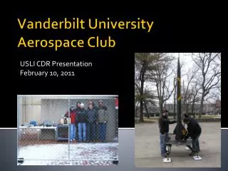
ULSI CDR Presentation Vanderbilt UniversityAerospace Club
Agenda • Changes since PDR • Final Vehicle Data and Key Design Features • Motor Selection and Performance • Rocket Mass • Recovery Information • Rocket and Payload Testing • Scale Model and Recovery Test Results • Payload System and Integration/Interfaces • Verification Status • Outreach Status Update
Changes Made Since PDR • Vehicle • Subscale launch used to determine full scale drag coefficient • Payload • Redesign of the ramjet attachment • Aerodynamic improvements • Activity Plan • Outreach even TWISTER was cancelled by the event organizers • Instead, winning middle school rocket teams will be invited to spend a day at Vanderbilt
Final Vehicle Dimensions • Length: 120” • Nominal Diameter: 6” • Four Sections(Lower Body Tube, Coupler Body Tube, Upper Body Tube, and Nosecone)
Key Design Features • Payload Bay Access Panel • Payload equipment needs to be accessed on the launch pad • Bolted to rocket after cryogen and kerosene are inserted securely into rocket • Payload Hardware • Cryogen Container • Evaporation creates the working pressure for the fuel • Kerosene Container • Injected into fuel line • Designed for both positive and negative G injection • Payload Hardware Retainment • Steel brackets bolted to wooden frame after containers are set in place
Key Design Features • Pathway for Fuel line and Instrumentation • Holes must be bored out of centering rings and bulk head • Steel piping used for fuel containment from kerosene tank to aft of rocket • Flexible tubing used to connect fuel line to ramjet • Additional Centering Ring • Needed for additional beam to record thrust from ramjet • Designed to maximize length inside of rocket
Key Design Features • Aerodynamic Sleeve • Carved foam: NACA 0015 airfoil • Used to drastically reduce drag from the thrust measuring beam
Motor Selection • CeasaroniPro-75 L1115 • Impulse: 5015 N-s • Burn Time: 4.48 s • Max Thrust: 1713.25 N • Thrust to Weight: 7.9 • Projected Altitude: 5170 ft • Rail Exit Velocity: 78 ft/s • Max Velocity: 575 ft/s • Max Acceration: 202 ft/s^2 • CG/CP/Margin: 89.6”/101”/1.87
Recovery System • Dual deployment controlled by redundant MAWD altimeters • Separation occurs: • at the nosecone joint • at the joint between the body tubes • Rocket descends as one unit • Parachutes • Main parachute • 144” dia. = 14 ft/s descent • Housed in nosecone • Drogue parachute • 48” dia. = 46 ft/s descent • Housed in the forward body tube, aft of the avionics bay
Testing • Rocket • MAWD altimeters using vacuum section • Shock cord attachments • Payload hardware retaining mechanism • Avionics bay wiring and connections • Rocket assembly time • Full Scale launch
Testing • Payload • Cryogen and Fuel Container Pressurization • Ensure the adequate pressurization of the fuel vessel, and the full scale launch will verify the adequate retention of both of the vessels during rocket launch. • Ramjet Mount • Ensure the ramjet will always remain securely attached to the rocket body airframe • Fuel Delivery and Injector • The flow rates and pressures will be optimized such that sustained combustion is achieved.
Testing • Payload • Flame Holder • The design of the flame holder will be verified first by ground based testing using the VASA fan to produce high wind speeds • Ramjet Body • Determine the amount of thrust produced and therefore the effectiveness of the ramjet engine at accelerating the airflow • Instrumentation • Used throughout ground based testing
Scale Model Test Flight • Length: 55.31” • Diameter: 4”
Recovery System Tests • Using calculated black powder charge sizes, a successful test of the recovery system was completed using last years rocket.
Payload System • The experiment that will be conducted during the rocket flight is the design validation of a scaled, subsonic ramjet engine • A pair of ramjet engines will be externally mounted to the aft-most section of the rocket • Identical except one will be ignited, while the other will not • Meant to prove that inexpensive rocket flights can serve as experimental test beds for engine and component design
Payload System • Ramjet Dimensions • Length: 12” • Diameter: 3” • Three sections • Diffuser: Inlet diameter of 2”, transitions to 3” with a length of 3” • Cylindrical Section: 3” diameter, 4” long • Nozzle: 1” long, 3” diameter cylindrical section with a 3” long transition to 1.5” • Testing Ramjet • Added flanges for modularity
Payload System • Cryogen Tank Used to Provide Pressure for Kerosene tank • Both Mounted Securely in Place
Payload Integration • Cyrogen tank, kerosene tank, and RDAS flight computer housed within its own dedicated payload bay. • Fuel tank housed in the upper portion of the bay to allow for longer fuel line length • Reduces likelihood of cryogen bubble and flameout during operation • Additional bulkheads with cutouts allow tanks to rest securely • Large, removable, external panel on payload bay allows easy access to tanks • Panel secured by 4, ¼-20 bolts • Additional epoxied bulkheads and 2, ¼” threaded rods reinforce structural integrity of the payload bay • RDAS flight computer mounted on board between threaded rods • Installed vertically, sliding on rods through the bottom of the bay.
Payload Integration Payload electronics isolated at bottom (note the 3 screw switches) Kerosene tank will be mounted at top
Interfaces • External: • Shear pins to nosecone/upper bodytube and upper bodytube/payload bay • Screw switches to MAWD altimeters • Screw switch to RDAS • Screw switch to Cryogen battery • Bolts to payload bay panel • Ramjet to rigid mounting ring • Motor to motor tube • Igniter to motor • Rocket to launch pad • Internal: • Batteries to MAWD altimeters • MAWD altimeters to electric matches • Electric matches to ejection charges • Battery to RDAS • Battery to cryogen solenoid • RDAS to cryogen solenoid • Cryogen solenoid to fuel tank • Fuel tank to ramjet injectors
Status of Requirements Verification • Key requirements are outlined in the CDR document • All technical requirements are being met • The design as previously discussed is designed to meet all requirements
Outreach Activity 1: Cora Howe Middle School (completed November 10 2011) Outreach Activity 2: Wright Middle School, MNPS, Nashville, TN (Completed December 1, 2011) Outreach Activity 3: Bailey STEM Magnet Middle School, MNPS, Nashville, TN. (completed December 12-16, 2011) Outreach Activity 4: Visit to Vanderbilt for winning middle school student rocket teams (tentatively scheduled for March 15, 2012) Educational Engagement: Status
Outreach Impact • Student achievement increased in across all of the standards addressed by our learning activities. • Over the course of the week, the number of students who could correctly answer questions about Newton’s laws of motion and measurement principles more than doubled . • Although students struggled with the multiple-choice question on inquiry, they showed improvement on the more difficult short answer questions. • Based on this analysis, it is likely that many students struggled with the imaginative premise and difficult wording of the question we had created. Consequently, we will be revising it for future use.