
Uploaded by
inge
2 SLIDES
147 VUES
20LIKES
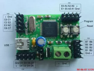
USB-Based Programmable Microcontroller Reset and Ground Configuration
DESCRIPTION
This document details the wiring and connections for a programmable microcontroller using a USB interface. It outlines the component layout, including pins CN1, CN2, and CN3 for power and ground, as well as programming connections for D0-D7. The reset functionality is also explained, providing a clear understanding of how to implement system restarts. Ideal for developers looking to customize and troubleshoot microcontroller setups in their projects.
Download
1 / 2
Télécharger la présentation 
USB-Based Programmable Microcontroller Reset and Ground Configuration
An Image/Link below is provided (as is) to download presentation
Download Policy: Content on the Website is provided to you AS IS for your information and personal use and may not be sold / licensed / shared on other websites without getting consent from its author.
Content is provided to you AS IS for your information and personal use only.
Download presentation by click this link.
While downloading, if for some reason you are not able to download a presentation, the publisher may have deleted the file from their server.
During download, if you can't get a presentation, the file might be deleted by the publisher.
E N D
Presentation Transcript
CN1 E0 A4 A2 A0 + E1 E5 A3 A1 Gnd CN2 + Gnd C0 C1 C2 E2 E3 NC C6 C7 Program Reset CN4 B7 B6 B5 B4 B3 B2 B1 B0 Gnd + USB Gnd D1 D3 D5 D7 + D0 D2 D4 D6 + Gnd CN3
More Related
Audio
Live Player