Download
1 / 1
10 likes | 148 Vues
Pedometer-like Electricity Generator. Contact: xu47@purdue.edu. Zexi Xu , Abbas Semnani Advisor: Dimitrios Peroulis Team: HANDLE. Assume the magnetic flux density B at the coil is : A ssume the coil is square shape with side length 33mm. The area of coil is:

E N D
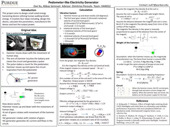
Pedometer-like Electricity Generator Contact: xu47@purdue.edu ZexiXu, Abbas Semnani Advisor: DimitriosPeroulis Team: HANDLE Assume the magnetic flux density B at the coil is: Assume the coil is square shape with side length 33mm. The area of coil is: Assume the distance between the magnet and coil is 1mm, Bo=0.1T is the magnetic flux density away from 1mm of the surface of the magnet. The magnetic flux density in the space is inversely proportional to square of the distance from the center of the magnet. Weight of the hammer: Assumption: when the hammer moves up, the magnitude of acceleration is g. The force from human is around 20N. L1=10cm,L2=2cm, F-Mg=Ma=Mg, F=2Mg In order to get the same amount of torque at one end. F*L1=2Mg*L1=20N*L2 M=0.2kg=200g Spring: Assumption: S1:S2=1:5; the human stepping frequency= 1Hz K=9.5(N/m) Circuit • Calculation • Vibration System • Hammer moves up and down totally 120 degrees/s. • The first level gear rotates 0.33round/s rotational velocity of second level gear1: (0.33round/s)*(2*pi*R0cm/round) / (2*pi*r1 cm/round) = 3.3round/s • 3. rotational velocity of first level gear1 • = rotational velocity of first level gear2 • = 3.3 round/s • rotational velocity of second level gear2 • = 3.3round/s*(2*pi*R1cm)/(2*pi*R2cm) • = 33round/s • AC Generator • From the graph, the magnetic flux density: • B is the magnetic flux density at the coil (vertical level). • If the magnet rotates in a constant speed (θ= ωt ),induced voltage is • (N is number of turns of the coil and S is the area of the coil) • Objective: Output power is 50mW • Assume the internal resistance and output load : • Output voltage is: • Output current is: • Effective voltage generated by the generator is: • maximum output voltage is • Induced Voltage is: • From previous calculation, we know that the AC generator rotates at a constant rate of 33 rounds/s Introduction This project aims to design small-sized energy harvesting device utilizing human walking kinetic energy. It involves four steps including, design the device, calculate the parameters, manufacture the device and test the output power. • Original Idea • How a pedometer works? • Hammer moves down with the movement of human step. • The arm of hammer touches the battery and closes the circuit and generates a pulse. • The pulse makes a count for the pedometer. • Hammer moves up and opens the circuit. • Inspiration from the pedometer hammer AC power generator When the hammer moves, the DC current goes through load and extra current charges the battery. When the hammer does not move, the battery can be the power supply for the load. • Design • . • How device works: • Hammer moves up and down with the movement of human step. • A set of gears rotates with movement of the hammer arm. • AC generator rotates with rotation of gears. • AC generator generates AC current and flows in the circuit. Parameters: R0=R1=2cm; r1=r2=2mm; Arm length=10cm; L=10cm; Reference A. Kobayashi, Y. Dohmen. Effect of bright light emitting diode (LED) flashlights and white lines on orientation and mobility performance of persons with sever peripheral field loss—A simulation study. International Congress Series, 2005, 1282:627-630 G. Stetten, D. Shelton, W. Chang, R. Tamburo, V. Chib, A. Cois, R. Hollis, A. Rizzi, L. Lobes, D. Schwatzman. Po-topic IV-16: Progress towards a clinically useful sonic flashlight. Academic Radiology, 2003,10,(8) : 959