
BOM/Assembly Diagram – Front View
BOM/Assembly Diagram – Front View. Barrel Bolt retainer. Main Unit, interior detailed on slide 3. Retainer mounting plate. Mounting hardware. Barrel Bolt, cut and attached inside main unit to solenoid shaft. BOM/Assembly Diagram – Rear View. Main Unit. Main Unit mounting plate.

BOM/Assembly Diagram – Front View
E N D
Presentation Transcript
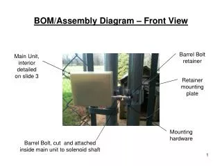
BOM/Assembly Diagram – Front View Barrel Bolt retainer Main Unit, interior detailed on slide 3 Retainer mounting plate Mounting hardware Barrel Bolt, cut and attached inside main unit to solenoid shaft
BOM/Assembly Diagram – Rear View Main Unit Main Unit mounting plate Hose clamp Hose clamp Retainer mounting plate
BOM/Assembly Diagram – Main Unit Receiver/Relay e-madeinchn.com p/n RR1-M/TCW200 (transmitter not shown here) Enclosure Allied Stk #: 736-1191 Battery Holder MPD p/n BH24AAW Cut barrel bolt coming in from outside unit. Mount to hole in solenoid shaft with screw/nut. AA Batteries (4) Solenoid from solenoidschina.com p/n AU1253L-A2.5 Screws mounting this main unit to its mounting plate below