Download
1 / 34
340 likes | 507 Vues
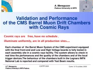
A. Meneguzzo Padova University & INFN. Validation and Performance of the CMS Barrel Muon Drift Chambers with Cosmic Rays. Cosmic rays are free, have no schedule , illuminate uniformly, are in all production sites.

E N D
A. Meneguzzo Padova University & INFN Validation and Performance of the CMS Barrel Muon Drift Chambers with Cosmic Rays Cosmic rays are free, have no schedule , illuminate uniformly, are in all production sites..... Each chamber of the Barrel Muon System of the CMS experiment equipped with the final front-end and Low and High Voltage boards is fully tested in each assembly site in a cosmic rays facility. The system allows to check in real time the perfomances and the quality of the chambers and of the local trigger devices.The behaviour of the chambers built in the Legnaro INFN National Lab is reported and compared with Test Beam results. ICATPP 2003
Barrel muon system V.Monaco – INFN Torino 8th IACTPP Conference, Como 6-10 October 2003 5 wheels 30o sectors with 4 stations 250 DT chambers 2.0x2.5 m2 (MB1) 4.0x2.5 m2 (MB4) ~2*105 channels 480 RPC chambers MB4 MB3 MB2 MB1 ICATPP 2003
“SuperLayer” (SL 2) (coord. in bending plane) 30 cm SL (non-bending plane) honeycomb panel SL 1 42mm S tA 13mm C W g s a b tB b/a ~ .65 tC continuous lines represent electrodes dotted lines represent equipotential surfaces tD CMS Drift Tube Chambers Within one SL 4 layers staggered by half a cell to solve L/R ambiguity 42mm A S S B 13mm 13mm W W g g s s C a a b b b/a ~ .65 b/a ~ .65 D continuous lines represent electrodes dotted lines represent equipotential surfaces continuous lines represent electrodes dotted lines represent equipotential surfaces ICATPP 2003
Muon system specifications V.Monaco – INFN Torino 8th IACTPP Conference, Como 6-10 October 2003 Muon identification (after >10 up to 2.4) Standalone momentum measurement Charge assignement (up to few TeV) Trigger on single and di-muons with variable Pt threshold up to 2.1 Bunch crossing assignment ICATPP 2003
Laboratori Nazionali di Legnaro (padova): DT chambers construction glue for I-beam LNL HV & LV boards Final chamber ICATPP 2003
Barrel Muon : DT chamber requirements • drift time vs position linearity in the cell • 100mm precision on wire position within a SL • <1mm betweenf SL • First Level Trigger • (Mean time technique on staggered layers) • Bunch crossing identification • Track segment reconstruction • Pt cut : sharp efficiency curve Muon track parameter - muon ID coverage up to IhI=1.1 - momentum & charge assignement • Resolution of 250mm/cell • Max Efficiency • Minimum Noise level Noise Efficiency Resolution Wire and Layer position accuracy SL F position accuracy we want to measure for each chamber ICATPP 2003
Chambers and Trigger set up at LNL Chamber under test Chamber under trigger test Local Trigger CCB Cosmic Rays : trigger set-up ICATPP 2003
Monitor and analysis SET UP The DAQ system is developed within the TRIDAS project; it has been used in the Test Beam 2000 , 2001, 2003 and at ISR (stoking area for final checks of all DT chambers). G.Maron et al. LNL Data Base Objectivity Flat File N.Toniolo LNL Analisys Off-line: -track reconstruction -trigger emulator -ntuples production with raw data and tracks information ORCA framework P.Ronchese et al., Pd MONITOR :on line analysis –occupancy -noise -efficiency -MT -Event Display ORCA framework Sara.Vanini et al., PD ICATPP 2003
Cell and drift time distribution checks 1800 V Strips 3600V good -1200 V bad but it can be recovered Drift time Bad cathod ICATPP 2003
channel Noise Noise of the channels in all layers of a chamber of all chambers channel channel 20 Hz/m ICATPP 2003
Noise vs Hv and noise vs Th Noise vs HV on the wire Noise vs FrontEnd Threshold ICATPP 2003
Efficiency cell efficiency in the layer efficiency inside the cell geometrical inefficiency 1.2/42= 3% for normal tracks I-beam wire 1.00 0.96 ICATPP 2003
Efficiency :angle & all chambers Dead angle= 90 98% 99% Mean SL Efficiency for the first 12 chambers ICATPP 2003
Efficiency :diagnostic Efficiency in a layer :last 8 cells low efficiency Efficiency as a function of position inside the cells No voltage on the cathods ICATPP 2003
t4 t3 t2 t1 d staggering Mean time fit with ‘time’ y t4 t3 t2 21000/ 380ns Vdrift=55mm/ns t1 d staggering semicolumn s= 1.6ns Wire position accuracy~70mm From the MeanTime distribution of the tracks in each semicolumn (semicell) we measure -the wire position accuracy from the width of the distribution of the Mean -the resolution and the resolution uniformity of the cells along the layer and in the SL Resolution=250mm Resolution smt=sqrt((s2-s trig_pm2) =3/2sl2 ICATPP 2003
MT: Layer displacement Example: layer 4 displaced of dx Dt Dt t4 t4 t4 t4 t3 t3 t3 t3 Dt = ( MT234R- MT234L) using the mean value of all MT234 ->good accuracy Layer 4 displacement -> Dx =Dt * vdrift t2 t2 t2 t2 t1 t1 t1 t1 d staggering d staggering d staggering d staggering Mean 378 ns Mean 383 ns ICATPP 2003
MT : signal wire propagation Measurement of the signal propagation along the wire vsignal=0.244 m/ns FEside vdrift=21/378=0.55mm/ns ICATPP 2003
MT summary Resolutionin the cell Drift velocityin the cell Accuracy on staggering and wire position s=1.7 ns =>> 66 mm For all chambers ICATPP 2003
MT vs angle The apparent drift velocity grows with y angle;it is constant for q F angle q angle ICATPP 2003
F Super Layers alignment All 4 point tracks, |f| < 20o 62215 mm build 4 point segment in each single SL MB3_12 x2 Extrapolate to the middle plane of the chamber x1 -3.80.1 mrad before alignment corrections ICATPP 2003
Layer alignement :7 point fit residuals <>=-1755 mm SL f1 <>=205 mm MB3_12 <>=395 mm SL f2 <>=655 mm ICATPP 2003
C2 fit vs SLs displacement c2 / NDOF all but one layer included (before layer alignment) 8515 mm Layer 1 excluded before layer alignment -0.50.1 mrad all layers included after layer alignment after alignment corrections ICATPP 2003
DT Chamber performance in Test Beam 192 micron Hit rate in SL1 is 3.5 (1.7 for SL 2) larger than the worst case at LHC (shown SL1) MB2 :TEST BEAM 2001 Resolution and Plateau knee Drift cell effic.&resolution With increasing Background CMS Note 2003/007 192 micron ICATPP 2003
* * * * * * * * * * * * * N H H L BTI outer * * * * * * * * * * * * * TRACO TSS/TSM Hi HH HL (LH) Ho * * BTI inner * N H H H * DT Chambers: 1st Level Trigger SL2 BTI outer SL1 BTI inner H 4 points track L 3 points track ICATPP 2003
First Level Trigger set-up: functionality tests with cosmic rays The first final set up of the First Level Trigger has been tested on a MB3 chamber with a muon bunched beam at Cern in may 2003 (the test was successfully and preliminary results show perfect behaviour). The set up was first assembled and its functionaly checked at the assembly site in LNL. Here I presents the on line results of these first preliminary tests that showed us that the set up was correctly working. The real performance of the 1st Level Trigger have been studied on the test beam run and will come out soon. (Results of the performance of the BTI part of the 1st Level Trigger from Test Beam and with Magnetic field are in the CMS note01-051) output triggers with 3(L) or 4(H) hits trigger tracks in each SL ->correlated trigger Bunch crossing identification Angle trigger -450 450 Angle track ICATPP 2003
Bunched TB 2003 DTchamberTriggerPreliminary Bunched TB 2003 DTchamberTriggerPreliminary Bunched TB 2003 DTchamberTriggerPreliminary trig. at efficiency = total# of events Event= scintillator + 2 hits in beam region trig. at 14bx efficiency = total# of events Event= scintillator + 2 hits in beam region trig. at 14bx efficiency = total# of events Event= scintillator + 2 hits in beam region trig. at 14bx efficiency = total# of events Event= scintillator + 2 hits in beam region trig. at 14bx efficiency = total# of events Event= scintillator + 2 hits in beam region tracks hitting 2 I-beams tracks hitting 2 I-beams tracks hitting 2 I-beams tracks hitting 2 I-beams tracks hitting 2 I-beams Preliminary DT Trigger Performance - Sara Vanini SIF 2003 ~ 98-99 % efficiency up to 350 ~ 98-99 % efficiency up to 350 ~ 98-99 % efficiency up to 350 ~ 98-99 % efficiency up to 350 ~ 98-99 % efficiency up to 350 “EMULATOR” is a SW package that emulates the full chain of the Trigger Chips and Boards. It works offline and need as input the times recorded by the TDCs. “Emulator “ is not the CMS simulation,it should reproduce exactly the Trigger data. To compare with the expected performance as shown in the Trigger TDR we should compare with the full track reconstruction from TDC data. However this first result is in excellent agreement with what we expect. “EMULATOR” is a SW package that emulates the full chain of the Trigger Chips and Boards. It works offline and need as input the times recorded by the TDCs. “Emulator “ is not the CMS simulation,it should reproduce exactly the Trigger data. To compare with the expected performance as shown in the Trigger TDR we should compare with the full track reconstruction from TDC data. However this first result is in excellent agreement with what we expect. “EMULATOR” is a SW package that emulates the full chain of the Trigger Chips and Boards. It works offline and need as input the times recorded by the TDCs. “Emulator “ is not the CMS simulation,it should reproduce exactly the Trigger data. To compare with the expected performance as shown in the Trigger TDR we should compare with the full track reconstruction from TDC data. However this first result is in excellent agreement with what we expect. “EMULATOR” is a SW package that emulates the full chain of the Trigger Chips and Boards. It works offline and need as input the times recorded by the TDCs. “Emulator “ is not the CMS simulation,it should reproduce exactly the Trigger data. To compare with the expected performance as shown in the Trigger TDR we should compare with the full track reconstruction from TDC data. However this first result is in excellent agreement with what we expect. “EMULATOR” is a SW package that emulates the full chain of the Trigger Chips and Boards. It works offline and need as input the times recorded by the TDCs. “Emulator “ is not the CMS simulation,it should reproduce exactly the Trigger data. To compare with the expected performance as shown in the Trigger TDR we should compare with the full track reconstruction from TDC data. However this first result is in excellent agreement with what we expect. ICATPP 2003
CONCLUSIONs The results of the tests performed in the production site with Cosmic Rays of each Barrel Muon Drift Chamber of the CMS experiment are very good andconfirms the 2000(cms note01-051) ,2001 (cms note03-07) and 2003 Test Beam results: Noise <25 Hz/m Efficiency uniform 99% / layer cell layer vs phi angle vs theta angle Resolution ~ 250m/cell 100m/SL Mean Time: cell layer phi angle theta angle Layer position accuracy< 110 m all Layers/SL SLs F position accuracy< 1mm linear fit Trigger tests with cosmicgood Cosmic rays are free, have no schedule , illuminate uniformly, are in all production sites. ICATPP 2003
help1 The Installation Task The Barrel Muon system comprises 250 chambers in 7 flavors: 60 MB1 3SL 2 RPC ~2.0 x 2.54 m2 960kg 60 MB2 3SL 2 RPC ~2.5 x 2.54 m2 1200kg 60 MB3 3SL 1 RPC ~3.0 x 2.54 m2 1300kg 40 MB4 2SL 1 RPC ~4.2 x 2.54 m2 1800kg 10 MB1 2SL 1 RPC 10 MB2 2SL 1 RPC 10 MB3 2SL 1 RPC 4 3 5 2 6 1 7 12 8 11 9 10 F SL SL Honeycomb MB4 (Torino) Have two Superlayers only F SL 10 Sectors will be installed in SX5 => 210 Chambers(310 RPCs). Sectors 1 and 7 are used for the lowering fixture and will be installed in UX5 => 40 Chambers(60 RPCs). ICATPP 2003
42 mm Help cell S g C s a b 13mm W b/a ~ .65 continuous lines represent electrodesdotted lines represent equipotential surfaces the presence of the grounded Al plates and beams between S and C makes the position of the g equipotential quite independent of the Voltages of s and c Vc ( and Vs) must generate in the region between c and g ( and between g and s ) an E field between 1 and 2 KV/cm to saturate the drift velocity the position of the s equipotential depends on the cell geometry (i.e. on the strip width and on the wire radius) Vw-Vs determines the GAIN in the gas : the request of a gain of ~ 10^5 determines the position of the s equipotential to be ~ 2.5 mm from the wire ICATPP 2003 LHCC Comprehensive Review 10/2/01 CMS MUONS: Drift Tubes and Alignment fabrizio
Help schedule LNL 5/9/2003 96 SL 32 CH Aachen 15/8 102 SL 34 Madrid 10/9 120 SL 34 CH 100 ch out of 210 Chambers at ISR MB1 20 by dec.03 29 MB2 28 38 MB3 25 30 Total 73 97 These figures can imply that all the dressing will be done for all chambers at ISR (to be agreed) ICATPP 2003
Help BTI * * a a * * * Shift registers * b * * a +b = T ICATPP 2003
Help ISR ICATPP 2003
Help TB2003 Traco CCB BX Efficiency -2 HH HL LL drop of correlated efficiency at large angles due to geometrical cuts (single BTI 56o traco 42o) Ho Hi Lo Li 15 DT Trigger Performance - Sara Vanini
Help TB2000 BTI BW .05 .1 .16 .21 .26 Bn 1.15 .96 .19 .77 .38 .56 BTI test in Magnetic Field (test beam 2000, CMS note 2001/051) Prob. of one/4 layers affected by delta 16%, more than one 4% B (TESLA) longitudinal component CMS TN 051 2001 .31 H-trig = 4/4 layers L-trig = 3/4 layers BTI n BTI n+1 ICATPP 2003 B (TESLA) radial component BTIs overlap