WSN Platforms: Hardware & Software
WSN Platforms: Hardware & Software. Murat Demirbas Lecture uses some slides from tutorials prepared by authors of these platforms. Why use a WSN?. Ease of deployment Wireless communication means no need for a communication infrastructure setup Drop and play Low-cost of deployment

WSN Platforms: Hardware & Software
E N D
Presentation Transcript
WSN Platforms: Hardware & Software Murat Demirbas Lecture uses some slides from tutorials prepared by authors of these platforms
Why use a WSN? • Ease of deployment • Wireless communication means no need for a communication infrastructure setup • Drop and play • Low-cost of deployment • Nodes are built using off-the-shelf cheap components • Fine grain monitoring • Feasible to deploy nodes densely for fine grain monitoring
Outline • Hardware • RFID, Spec • Mica2, XSM, Telos • Stargate • Software • TinyOS • Simulation • TOSSIM • Prowler
Types of sensor platforms • RFID equipped sensors • Smart-dust tags • typically act as data-collectors or “trip-wires” • limited processing and communications • Mote/Stargate-scale nodes • more flexible processing and communications • More powerful gateway nodes, potentially using wall power
Grain-sized nodes • Powered by inductive coupling to a transmission from a reader device to transmit a message back • Available commercially at very low prices • Computation power is severely limited • Can only trasmit stored unique id and variable • Hard to add any interesting sensing capability
Spec Mote (3/6/2003) • size: 2x2.5mm, AVR RISC core, 3KB memory, FSK radio (CC1000), encrypted communication hardware support, memory-mapped active messages
Matchbox-sized nodes • Mica series, XSM node, Telos • 8-bit microprocessor, 4MHz CPU • ATMEGA 128, ATMEL 8535, or Motorola HCS08 • ~4Kb RAM • holds run-time state (values of the variables) of the program • ~128Kb programmable Flash memory • holds the application program • Downloaded via a programmer-board or wirelessly • Additional Flash memory storage space up to 512Kb.
Mica2 and Mica2Dot 1 inch • ATmega128 CPU • Self-programming • Chipcon CC1000 • FSK • Manchester encoding • Tunable frequency • Low power consumption • 2 AA battery = 3V
Basic Sensor Board • Light (Photo) • Temperature • Prototyping space for new hardware designs
Light (Photo) Temperature Acceleration 2 axis Resolution: ±2mg Magnetometer Resolution: 134mG Microphone Tone Detector Sounder 4.5kHz Mica Sensor Board
PNI Magnetometer/Compass • Resolution: 400 mGauss • Three axis, under $15 in large quantities
Used for ranging Up to 2.5m range 6cm accuracy Dedicated microprocessor 25kHz element Ultrasonic Transceiver
Total Solar Radiation Photosynthetically Active Radiation Resolution: 0.3A/W Relative Humidity Accuracy: ±2% Barometric Pressure Accuracy: ±1.5mbar Temperature Accuracy: ±0.01oC Acceleration 2 axis Resolution: ±2mg Designed by UCB w/ Crossbow and UCLA Mica Weather Board Revision 1.5 Revision 1.0
MicaDot Sensor Boards • “Dot” sensorboards (1”diameter) • HoneyDot: Magnetometer • Resolution: 134 mGauss • Ultrasonic Transceiver • Weather Station
XSM node platform • Derived from Mica2 mote • Better sensor & actuator range • 4 Passive Infrared: ~ 25m for SUV • Sounder: ~10m • Microphone: ~ 50m for ATV • Magnetometer: ~ 7m for SUV • Better radio range ~30m • Other features: • Grenade timer • Wakeup circuits (Mic, PIR) • Adjustable frequency sounder • Integrated Mag Set/Reset
Telos Platform • Low Power • Minimal port leakage • Hardware isolation and buffering • Robust • Hardware flash write protection • Integrated antenna (50m-125m) • Standard IDC connectors • Standards Based • USB • IEEE 802.15.4 (CC2420 radio) • High Performance • 10kB RAM, 16-bit core, extensive double buffering • 12-bit ADC and DAC (200ksamples/sec) • DMA transfers while CPU off
TelosMeeting the Low Power Goal All values measured at room temperature (approximately 25oC) at 3V supply voltage Source: “Telos: Enabling Low Power Wireless Sensor Network Research”To appear, IPSN/SPOTS, April 2005
200ksamples/sec sampling rate, DMA transfers, DAC Increased performance & functionality over existing designs New “link quality indicator” predicts average packet loss Packet Success Average LQI RSSI Distance (ft) Distance (ft) Distance (ft) Telos Performance Flat field range test @ 4” off ground (125m @ 1m elevation)
Brick-sized node: Stargate • Mini Linux computers communicating via 802.11 radios • Computationally powerful • High bandwidth • Requires more energy (AA infeasible) • Used as a gateway between the Internet and WSN
Manufacturers of Sensor Nodes • Crossbow (www.xbow.com) • Mica2 mote, Micaz, Dot mote and Stargate Platform • Intel Research • Stargate, iMote • Moteiv – Telos Mote • Dust Inc • Smart Dust • Cogent Computer (www.cogcomp.com) • XYZ Node (CSB502) in collaboration with ENALAB@Yale • Sensoria Corporation (www.sensoria.com) • WINS NG Nodes • Millenial Net (www.millenial.com) • iBean sensor nodes • Ember (www.ember.com) • Integrated IEEE 802.15.4 stack and radio on a single chip
Energy constraint Unreliable communication Unreliable sensors Ad hoc deployment Large scale networks Limited computation power Distributed execution Nodes are battery powered Radio broadcast, limited bandwidth, bursty traffic False positives Pre-configuration inapplicable Algorithms should scale well Centralized algorithms inapplicable Difficult to debug & get it right Challenges in sensor networks
Precise clock at each node Atomic broadcast primitive Geometry New applications Timers, synchronized clocks All recipients hear the same message at the same time Dense nodes over 2D plane Tracking, spatial querying, geographic routing, localization, network reprogramming, etc. Opportunities in sensor networks
Outline • Hardware • RFID, Spec • Mica2, XSM, Telos • Stargate • Software • TinyOS • Simulation • TOSSIM • Prowler
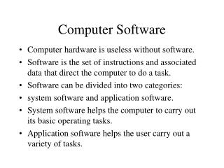
TinyOS • most popular operating system for WSN • developed by UC Berkeley • features a component-based architecture • software is written in modular pieces called components • Each component denotes the interfaces that it provides • An interface declares a set of functions called commands that the interface provider implements and another set of functions called events that the interface user should be ready to handle • Easy to link components together by “wiring” their interfaces to form larger components • similar to using Lego blocks
TinyOS • provides a component library that includes network protocols, services, and sensor drivers • An application consists of • a component written by the application developer and • the library components that are used by the components in (1) • An application developer writes only the application component that describes the sensors used in the application, the middleware services configured with the appropriate parameters based on the needs of the application
Benefits of using TinyOS • Separation of concerns • TinyOS provides a proper networking stack for wireless communication that abstracts away the underlying problems and complexity of message transfer from the application developer • E.g., MAC layer • Concurrency control • TinyOS provides a scheduler that achieves efficient concurrency control • An interrupt-driven execution model is needed to achieve a quick response time for the events and capture the data • For example, a message transmission may take up to 100msec, and without an interrupt-driven approach the node would miss sensing and processing of interesting data in this period • Scheduler takes care of the intricacies of interrupt-driven execution and provides concurrency in a safe manner by scheduling the execution in small threads.
Benefits of TinyOS • Modularity • TinyOS’s component model facilitates reuse and reconfigurability since software is written in small functional modules. Several middleware services are available as well-documented components • Over 500 research groups and companies are using TinyOS and numerous groups are actively contributing code to the public domain
TinyOS • Microthreaded OS (lightweight thread support) and efficient network interfaces • Two level scheduling structure • Long running tasks that can be interrupted by hardware events • Small, tightly integrated design that allows crossover of software components into hardware
msg_send_done) msg_rec(type, data) TinyOS Concepts • Scheduler + Graph of Components • constrained two-level scheduling model: threads + events • Component: • Commands • Event Handlers • Frame (storage) • Tasks (concurrency) • Constrained Storage Model • frame per component, shared stack, no heap • Very lean multithreading • Efficient Layering Events Commands send_msg(addr, type, data) power(mode) init Messaging Component internal thread Internal State TX_packet(buf) Power(mode) init RX_packet_done (buffer) TX_packet_done (success)
Application = Graph of Components Route map Router Sensor Appln application Active Messages Example: ad hoc, multi-hop routing of photo sensor readings Serial Packet Radio Packet packet Temp Photo SW 3450 B code 226 B data HW UART Radio byte ADC byte clock RFM bit Graph of cooperating state machines on shared stack
Radio Packet packet Radio byte byte RFM bit TOS Execution Model • commands request action • ack/nack at every boundary • call command or post task • events notify occurrence • HW interrupt at lowest level • may signal events • call commands • post tasks • tasks provide logical concurrency • preempted by events data processing application comp message-event driven active message event-driven packet-pump crc event-driven byte-pump encode/decode event-driven bit-pump
Event-Driven Sensor Access Pattern • clock event handler initiates data collection • sensor signals data ready event • data event handler calls output command • device sleeps or handles other activity while waiting • conservative send/ack at component boundary command result_t StdControl.start() { return call Timer.start(TIMER_REPEAT, 200); } event result_t Timer.fired() { return call sensor.getData(); } event result_t sensor.dataReady(uint16_t data) { display(data) return SUCCESS; } SENSE LED Photo Timer
TinyOS Commands and Events { ... status = call CmdName(args) ... } command CmdName(args) { ... return status; } event EvtName(args) { ... return status; } { ... status = signal EvtName(args) ... }
Tasks events commands Interrupts Hardware TinyOS Execution Contexts • Events generated by interrupts preempt tasks • Tasks do not preempt tasks • Both essential process state transitions
Tasks • provide concurrency internal to a component • longer running operations • are preempted by events • able to perform operations beyond event context • may call commands • may signal events • not preempted by tasks { ... post TskName(); ... } task void TskName { ... }
Typical Application Use of Tasks • event driven data acquisition • schedule task to do computational portion event result_t sensor.dataReady(uint16_t data) { putdata(data); post processData(); return SUCCESS; } task void processData() { int16_t i, sum=0; for (i=0; i ‹ maxdata; i++) sum += (rdata[i] ›› 7); display(sum ›› shiftdata); }
Task Scheduling • Currently simple fifo scheduler • Bounded number of pending tasks • When idle, shuts down node except clock • Uses non-blocking task queue data structure • Simple event-driven structure + control over complete application/system graph • instead of complex task priorities
Maintaining Scheduling Agility • Need logical concurrency at many levels of the graph • While meeting hard timing constraints • sample the radio in every bit window • Retain event-driven structure throughout application • Tasks extend processing outside event window • All operations are non-blocking
CRCfilter RadioTiming ChannelMon The Complete Application SenseToRfm generic comm IntToRfm AMStandard RadioCRCPacket UARTnoCRCPacket packet noCRCPacket photo Timer MicaHighSpeedRadioM phototemp SecDedEncode SW byte SPIByteFIFO RandomLFSR HW ADC UART ClockC bit SlavePin
Programming Syntax • TinyOS 2.0 is written in an extension of C, called nesC • Applications are too • just additional components composed with OS components • Provides syntax for TinyOS concurrency and storage model • commands, events, tasks • local frame variable • Compositional support • separation of definition and linkage • robustness through narrow interfaces and reuse • Interpositioning • Whole system analysis and optimization
Components • A component specifies a set of interfaces by which it is connected to other components • provides a set of interfaces to others • uses a set of interfaces provided by others • Interfaces are bidirectional • include commands and events • Interface methods are the external namespace of the component provides StdControl Timer provides interface StdControl; interface Timer: uses interface Clock Timer Component uses Clock
Component Interface • logically related set of commands and events StdControl.nc interface StdControl { command result_t init(); command result_t start(); command result_t stop(); } Clock.nc interface Clock { command result_t setRate(char interval, char scale); event result_t fire(); }
Component Types • Configurations • link together components to compose new component • configurations can be nested • complete “main” application is always a configuration • Modules • provides code that implements one or more interfaces and internal behavior
Example1 • Blink application Blink Main configuration Blink { } implementation { components Main, BlinkM, TimerC, LedsC; Main.StdControl -> TimerC.StdControl; Main.StdControl -> BlinkM.StdControl; BlinkM.Timer -> TimerC.Timer[unique("Timer")]; BlinkM.Leds -> LedsC; } BlinkM Blink.nc TimerC LedsC
Example1 • BlinkM module: module BlinkM { provides interface StdControl; uses interface Timer; uses interface Leds; } implementation { command result_t StdControl.init() { call Leds.init(); return SUCCESS; } command result_t StdControl.start() { return call Timer.start(TIMER_REPEAT, 1000); } command result_t StdControl.stop() { return call Timer.stop(); } event result_t Clock.fire() { call Leds.redToggle(); return SUCCESS; } } Blink.nc Blink.nc
IntToRfm Photo TimerC Example2 configuration SenseToRfm { } implementation { components Main, SenseToInt, IntToRfm, TimerC, Photo as Sensor; Main.StdControl -> SenseToInt; Main.StdControl -> IntToRfm; SenseToInt.Timer -> TimerC.Timer[unique”Timer”]; SenseToInt.ADC -> Sensor; SenseToInt.ADCControl -> Sensor; SenseToInt.IntOutput -> IntToRfm; } Main StdControl SenseToInt ADCControl ADC IntOutput Timer
Nested Configuration includes IntMsg; configuration IntToRfm { provides { interface IntOutput; interface StdControl; } } implementation { components IntToRfmM, GenericComm as Comm; IntOutput = IntToRfmM; StdControl = IntToRfmM; IntToRfmM.Send -> Comm.SendMsg[AM_INTMSG]; IntToRfmM.SubControl -> Comm; } StdControl IntOutput IntToRfmM SendMsg[AM_INTMSG]; SubControl GenericComm
IntToRfm Module command result_t StdControl.start() { return call SubControl.start(); } command result_t StdControl.stop() { return call SubControl.stop(); } command result_t IntOutput.output(uint16_t value) { ... if (call Send.send(TOS_BCAST_ADDR, sizeof(IntMsg), &data) return SUCCESS; ... } event result_t Send.sendDone(TOS_MsgPtr msg, result_t success) { ... } } includes IntMsg; module IntToRfmM { uses { interface StdControl as SubControl; interface SendMsg as Send; } provides { interface IntOutput; interface StdControl; } } implementation { bool pending; struct TOS_Msg data; command result_t StdControl.init() { pending = FALSE; return call SubControl.init(); }