NVIS Antennas
NVIS Antennas. N ear V ertical I ncidence S kywave Hap Griffin WZ4O November 2012. HF Propagation via the Ionosphere. Skywave. Groundwave. The Situation…. Much HF operation is “localized” in nature on 75 and 40 meters.


NVIS Antennas
E N D
Presentation Transcript
NVIS Antennas Near Vertical Incidence Skywave Hap Griffin WZ4O November 2012
HF Propagation via the Ionosphere Skywave Groundwave
The Situation… • Much HF operation is “localized” in nature on 75 and 40 meters. • State and regional nets commonly have check-ins at 50 to 300 mile range. • Too far for groundwave and too close for optimal low angle skywave communications. • High angle of skywave radiation is desirable for this situation. • Omni-directional antennas also desirable.
The Physics… • MUF – Maximum Usable Frequency – Maximum frequency signal that will reflect from ionosphere over any given path…higher frequency signals pass through the ionosphere into space. • MUF is always changing – depends on season and time of day. • Critical Angle of Radiation – For any given frequency, there is a maximum angle at which that signal will reflect off the ionosphere…signals at higher angles will pass through into space. • Critical angle for any frequency is always changing
The Physics… • Vertical Incidence Critical Frequency – The Maximum Usable Frequency for local high angle skywave communications • Vertical-Incidence Critical Frequency averages between 2 and 13 MHz for the F-layer, ranging from 2 MHZ during nighttime at the lowest point of the solar cycle to 13 MHz during the daytime at the highest point of the solar cycle
Which Bands are Useful For High Angle Communications? • Remember that Vertical-Incidence Critical Frequency averages between 2 and 13 MHz, so we can eliminate 20m band and all higher bands. • 30m is marginal, and 160m requires a huge antenna , so we can eliminate those as well. • That leaves us with the 80m, 60m, and 40m bands that are traditionally used for reliable NVIS operation.
Dipole at 1 Wavelength Above Ground = 140 Ft Feedpoint Impedance = 74 + j08
Dipole at 0.7 Wavelength Above Ground = 98 Ft Feedpoint Impedance = 70 + j30
Dipole at 0.5 Wavelength Above Ground = 70 Ft Feedpoint Impedance = 71 – j0
Dipole at 0.3 Wavelength Above Ground = 42 Ft Feedpoint Impedance = 100 + j32
Dipole at 0.1 Wavelength Above Ground = 14 Ft Feedpoint Impedance = 23 + j39
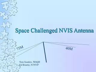
NVIS Dipole at 0.15 Wavelength Above Ground 75 meters - 37 feet 40 meters - 20 feet
NVIS Dipole at 0.15 Wavelength Above Ground With Reflector 75 meters - 37 feet 40 meters - 20 feet Reflector 5% longer than radiating dipole
NVIS 40 meter Dipole at 1/20th Wavelength Above Ground With Reflector
NVIS Full Wave Loop at 0.15 Wavelength Above Ground With Reflector
Conclusions… • Mounted at less than a half-wavelength high, dipoles exhibit almost omni-directional patterns • For localized operation on 80/40 meters, a low NVIS-style antenna may be best • We may already have an NVIS antenna and not realize it! • NVIS is only practical on 80 and 40 meters. • NVIS antennas generally have less noise – distant lightning static is coming in at low angles • So, for operation on statewide or regional nets, try LOWERING your antenna on 80/40 meters.