Download
1 / 21
210 likes | 369 Vues
Longitudinal Beam Dynamics Studies in EMMA. FFAG’10 Jimmy Garland October 2010 The University of Manchester The Cockcroft Institute. Introduction.

E N D
Longitudinal Beam Dynamics Studies in EMMA FFAG’10 Jimmy Garland October 2010 The University of Manchester The Cockcroft Institute
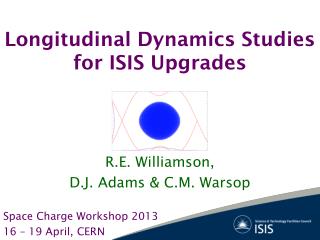
Introduction • EMMA (Electron Model for Many Applications) is the worlds first non-scaling FFAG accelerator and is being commissioned at the STFC Daresbury Laboratory in the UK. • Basics parameters:
Time of Flight in EMMA • In contrast to scaling FFAG’s, in a non-scaling FFAG the path length variation, hence time of flight (ToF) variation, is approximately parabolic as a function of the particle momentum.
Time of Flight in EMMA • ToF was measured in EMMA by comparing BPM signal of the beam with the RF waveform. 55.306 ns at 14 MeV and 55.339 ns at 18 MeV BPM Signal Integrated to find zero cross Direct BPM Signal BPM Signal compared to RF Waveform Relative phase wrt RF as a function of turn number h= harmonic number φ = relative phase FRF = RF frequency
Fundamentals of the Code • This parabolic shape of the time of flight curve as a function of energy can be approximated by a 2nd order Taylor expansion: • The constants P1, P2 and P3 then represent a particular lattice for EMMA based on a particular simulation given by a code such as MADX. • Built a simple longitudinal code to simulate the longitudinal properties of the beam. • No Hamiltonian formulation, instead based on the ToF per cell as a function of Energy curve given by Shinji Machida’s code. • Basic input parameters are: • The EMMA lattice containing 42 cells and 19 cavities • The RF frequency, phase and voltage of the cavities • The initial energy ‘E’ and the longitudinal coordinate ‘l’ with respect to a reference orbit moving with a time of flight corresponding to a specified RF frequency
Fundamentals of the Code • ToF was measured in EMMA for 2 lattices of equivalent energies of 14 and 18 MeV with no acceleration. • Scaled the ToF curve acquired from Machida’s code with respect to the data measured from EMMA in order to model the real machine more accurately.
RF Buckets • If an RF frequency is chosen which corresponds to a point on the ToF curve we can select acceleration buckets at particular energies.
Buckets and the Gutter • In fact in an ns-FFAG we can allow the particles to be accelerated in the so called “gutter” between buckets. This is known as “serpentine acceleration”.
Buckets and the Gutter • Modeled the acceleration as a function of voltage in the cavities…
Buckets and the Gutter • Above some voltage the serpentine channel is opened up…
Bucket to the Gutter • There should be a minimum voltage required for acceleration in the gutter, below which there is no gutter channel available. • Well within the 2.3MV per turn limit of the RF.
Phase Errors • Why haven’t we seen any convincing acceleration in EMMA yet? • Possibly phase error on cavities?... • Doesn’t appear to affect the serpentine acceleration over many turns (~100). (5, 10, 20 and 50% error). However what about resonance crossing in real mahine? (please note incorrect scale for energy) • However the probability of getting acceleration appears to be about 1/3…..
Phase Errors • Other 2/3 of the time we get… …I can’t explain this yet. Any comments?
Synchrotron Tune • Synchrotron tune was measured in the machine Figure courtesy of Shinji Machida I calculate the synchrotron tune to be approximately 0.07 under the same conditions: 1MV per turn Tune is approximately 0.04 as measured in the machine.
Synchrotron Tune • Could this mean that we have some uncertainty in our knowledge of the RF voltage in the cavities? A value of approximately 0.38MV per turn gives a tune of 0.04 in simulation. . Perhaps my code has problems…
Conclusions • Writing this code has been valuable for learning simple longitudinal dynamics. • I have modeled (hopefully correctly!) some important properties of EMMA such as the serpentine acceleration. • Next steps are to start to bench mark my code with other codes to work out any errors. Also possibly write a full canonical model (Hamiltonian formulation). • Need to work out why model and measurement disagree on synchrotron tune. • When EMMA runs again after Christmas, hopefully we will see serpentine acceleration! Thanks for listening! Special thanks to Shinji Machida and Hywel Owen for all their guidance.
Backup Slides Synchrotron tune is proportional to the square root of the cavity voltage
Backup Slides • If the frequency matches the bottom of the ToF curve we can get a much larger channel. And therefore accept a wider range of phases.
Backup Slides • It appears that the initial particle phase is also important and affects the acceleration. Is this sensitivity correct? If so it might affect the acceleration in the machine.