Commentary
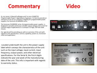
Video. Hi, my name is Edward Guillergan and I’m one of AMETEK Programmable Power’s Applications Engineers. I’m here to provide an overview of one of our company’s flagship DC programmable power supplies, the Sorensen DLM600W series.

Commentary
E N D
Presentation Transcript
Video Hi, my name is Edward Guillergan and I’m one of AMETEK Programmable Power’s Applications Engineers. I’m here to provide an overview of one of our company’s flagship DC programmable power supplies, the Sorensen DLM600W series. The Sorensen DLM600W series of programmable power supplies is designed to provide continuous variable output voltage and current for a broad range of applications in a compact 1U high, half rack wide chassis. Our agenda will be providing you with an overview of the unit with regards to the specification, control, capability, power on, functional check and application. Commentary -Located underneath the unit is the power supply label which conveys the characteristics of the unit such as the input voltage, input current, input frequency, output power, and other electrical specifications. For the Serial #, the first 4 digits indicate the year and week of the manufacturing date of the unit. This info is important with regards to warranty status.
Video -This is the standard front panel of the DLM600W model series. We are showing the DLM40-15 version. This designation indicates the unit range of 0-40V and 0-15A. There is a variety of voltage/current combinations ranging up to 300V max and 75A max at 600W output. Analog programming/monitoring for voltage/current comes standard. Remote interface options also available include optically isolated analog programming/monitoring for voltage/current, GPIB/RS232, and ethernet/RS232. Commentary -This is the rear panel of the unit. The output portion is protected by a safety cover. The output terminal configuration will vary depending if the unit is low voltage (5-60V) or high voltage (80-300V). -This particular unit has the GPIB/RS232 remote interface.
Commentary Video -As far as remote interfaces go, a standard unit comes with the analog programming/monitoring. You can also have the GPIB/RS232 option, which I just showed you, the ethernet/RS232 option, and the optically isolated analog programming/monitoring. Note that you can only choose one of these options as they cannot be combined. -Use a power cord with the unit for the AC input connection. The DLM600W model series has a universal auto ranging AC input at 90-132V and 180-265V. -For the time being, make sure there aren’t any connections on the rear panel other than the power cord. Now we’re ready to power up the unit.
Commentary Video -The front panel control consists of the Power On/Off button. Once you press the button, the power supply will execute a boot up routine for about 7 seconds and as you can see, all the LEDs are lit up with the fans running at maximum speed. -At this point, you can now start using the unit. I will go through further details and examples conveying the functions of the unit. -After being booted up, this conveys the default settings of the unit shipped straight from the factory. -These are the Voltage (1) and Current (2) knobs. They are 10 turn potentiometers. Since we don’t have a load connected at the moment, make sure you set at least a small amount of current before you start increasing the voltage so you can see a voltage output. 1 2 -Before we turn the output on, we’ll set our Voltage and Current limit values using the front panel knobs. If we press and hold the V/I (Voltage/Current) Preview button, we can see what our output will be when we turn on the output. -As you can see from the DC VOLTS and DC AMPS display, we have set the voltage to 25V and the current limit to 15A. The actual output will vary depending on what your load is.
Commentary Video -Next, we’ll configure the Over Voltage Protection. The OVP Set is an adjustable potentiometer which you can configure using an insulated flathead screwdriver. -The default factory setting of the OVP is 110% of the rated voltage of the unit, in our case, 44V. You can configure it between 5-110% of the power supply voltage rating. -You can preview the set point value by pressing and holding the OVP Preview button while adjusting. We’ll configure the OVP set point to 30V. -I will now power down the unit and set up a 2.4 ohm load. -We’ll then again power up the unit and turn on the output by pressing the Output button. As you can see, since we have a 2.4 Ohm load, our actual output is 25V and 10.43A. -We’ll increase the voltage to test out the OVP set point we set earlier at 30V. -As you can see, once the load starts drawing 30V, the OVP fault will activate causing the output to go to zero and OVP LED indicator to light up. The OVP function is helpful to protect loads not specced to handle certain voltages.
Video -Other LED indicators on the front panel include the FAULT LED. It can trigger from either over temperature shutdown, logic supply fault, cooling fan fault, or the other fault summaries listed in the manual. -The REM LED activates when you’re controlling the unit via remote interface (analog, GPIB/RS232, ethernet/RS232). -The EXT OFF LED activates when a shutdown signal is sent via remote interface (analog, GPIB/RS232, ethernet/RS232). This is an indicator to the user that the unit was shutdown remotely. -There’s also a LOCAL(REMOTE) button which will allow you to switch between Local and Remote interface control. Commentary -The DLM600W model series has 2 modes, constant voltage (CV) and constant current (CC). You can switch between modes continuously without interruption of the output. -Now I’ll show you an example of how the constant voltage (CV) and constant current (CC) operates. Which ever mode you’re in, it is indicated through the VOLTAGE (1)or CURRENT (2) LED on the front panel. -I still have my 2.4 ohm load set up at the output. Before I turn on the output, I will set my voltage to 23V and my current limit to 10A. I check the value using the V/I (Voltage/Current) PREVIEW button. Now, I can turn the output on using the OUTPUT button. 1
Commentary Video -As you can see, with the output on, my voltage is 23V and my current is 9.59A due to my 2.4 ohm load. -Anytime the load draws less then what I set my current limit to, 10A, the unit is in constant voltage mode which is indicative by the VOLTAGE (1) LED being lit up. -Now I will increase my voltage and the current will change as well with reference to the 2.4 ohm load. -Once my unit starts to draw what I set my current limit to, 10A, it will then switch to constant current mode as indicative by the CURRENT (2)LED being lit up. 1 2 -I have given you a basic intro to the Sorensen DLM600 model series. -Prior to use with your application, please reference the operation manual for safety instruction, wiring requirements, specifications, protection diodes, remote/local sense, remote/local programming.
Commentary Video For more information, please visit our website at www.programmablepower.com