Download
1 / 61
690 likes | 1.19k Vues
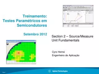
Treinamento : Testes Paramétricos em Semicondutores Setembro 2012. Cyro Hemsi Engenheiro de Aplicação. Section 2 – Source/Measure Unit Fundamentals. Agenda. Section #2 – SMU Fundamentals SMU Overview Low Current Measurement Sweep Measurements. SMU Overview.

E N D
Treinamento:Testes ParamétricosemSemicondutoresSetembro 2012 Cyro Hemsi Engenheiro de Aplicação Section 2 – Source/Measure Unit Fundamentals
Agenda • Section #2 – SMU Fundamentals • SMU Overview • Low Current Measurement • Sweep Measurements
What is a Source/Measure Unit (SMU)? Simplified equivalent circuit (2-wire measurements): Ideal Voltage Source Ammeter -Voltage or current source: spot, sweep, pulsed - Measure both voltage and current - + + - A High Force + V - Low Force Voltmeter Chassis Ground Ideal Current Source femtoamp and nanovolts Note: The tight integration of these measurement resources yields better accuracy and faster measurement than would an equivalent collection of separate instruments.
EXTRA What is an SMU? It’s Source/Measure Unit SMU = • SMU is a single or combination of DC sources and measurements. • Like power supply • V source • I source • Like multi meter • V measurement • I measurement • (Resistance measurement) • As a SMU • V source & I measurement • I source & V measurement DMM + Precision/Bipolar PS Power Supply Electronic Load +Voltage Quadrant 2 Quadrant 1 - Current + Current Quadrant 3 Quadrant 4 - Voltage
4070 series Agilent SMU history Agilent has more then 30 years of SMU experience. Bench-top SMU 4080 series 4062UX series B2900A series 4062A/B/C Modular SMU Parameter Analyzer E5260A/70B series HP 4142B Test System B1500A/05A 4155/56 series 4145 series 80 95 10 85 90 00 05 Year
Agilent Parametric Instruments E5260A Series & E5270B Modular Mainframes B1500A Automated test solutions for production & lab environments B1505A B2200A & B2201A E5250A Semiconductor Parameter/Device Analyzers Switching Matrices High-performance switching solutions for lab environments Single-box solutions with built-in user interface.
EXTRA Parameter Analyzers for High-End Device Test Agilent SMU Portfolio New B2900A Series Bench-top SMU B1500A New Generation of Parameter Analyzer up to 200V/1A and optional CMU/SPGU/WGFMU B1505ANew Power Device Solution up to 3000V/40A GeneralPurpose (Precision I/V characterization) Device, Components, Material General Purpose (Power Analysis) Battery Drain Functional Basic SMUs forGP & Basic Device Test TODAY E5270B Precision Modular SMUup to 8 slots (0.1fA resolution) E5260A High speed SMU up to 8 slots N678xA SMUs DC power analyzer (SMU module) U2722A/U2723AUSB type SMU module
Overview of the Agilent B1500A Complete capacitance measurement solution • QSCV using SMUs • CV module for 1 kHz to 5 MHz measurement • Built-in CV compensation • Automatic CV/IV switching • Agilent 4294A driver (for up to 110 MHz CV or Cf) Versatile design • Flexible: 10 module slots • Large touch screen display • Windows XP-based for easy workplace integration Integrated fast pulsed measurement • Voltage pulsing and fast IV measurement in one module • Fast: 1 ms spot and 100 ms 10-pt sweep measurement • Test up to 10 channels in parallel Advanced measurement functions • Linear/binary search • Multi-channel sweep • List Sweep • Parallel test • Direct control mode • Range management • Curve tracer function Leading edge non-volatile memory test • ±40 V pulsing capability • 0.4 mV force voltage resolution • 10 ns pulse widths • Arbitrary waveform creation • Up to 10 independent pulse channels EasyEXPERT software • Intuitive interface • >240 furnished application tests • Built-in test sequencing & wafer prober control • Easy data export
Agilent EasyEXPERT 4.x Software (on B1500A) Innovative task-based approach to parametric test Measure, append and repeat functions Over 240 furnished application tests Microsoft Windows-based EasyEXPERT software Built-in semi-auto wafer prober drivers Supported Functions: 1. Sweep 2. Multi-channel sweep 3. List sweep 4. Time sampling 5. 1 kHz to 5 MHz CV 6. Quasi-static CV 7. Direct control 8. HV-SPGU Control Integrated switching matrix control for the B2200A, B2201A and E5250A Standby mode for circuit debug “My Favorite Setup” feature allows users to customize application tests Intuitive GUI-based application test setup windows “Tracer Mode” supports knob-sweep curve tracer functionality Can automatically export measurement data to external drives Data and setup information can be automatically saved or selectively saved after each measurement “Quick Test” utility supports test sequencing without programming
The B1500A Meets DC, Fast IV & Fast Pulsed IV Measurement Challenges Multi-frequency capacitance measurement unit (MFCMU) Medium power SMU (MPSMU) High resolution SMU (HRSMU) High power SMU (HPSMU) Waveform Generator/ Fast Measurement Unit (WGFMU) High-Voltage Semicon-ductor Pulse Generator Unit (HV-SPGU) 4.2 Amp ground unit (GNDU) Ten slot modular mainframe All SMU types are Kelvin (separate force and sense inputs)
B1511A Medium Power SMU (MPSMU) B1511A MPSMU Maximum voltage +/- 100V (at 20mA) Maximum current +/- 100mA (at 20V) Voltage Measurement 0.5uV to 100V Current Measurement 10fA to 100mA Pulse Function (SMU pulse) Pulse Width 500us to 2s Pulse Period 5ms to 5s Maximum Power 2W Slot Consumption 1slots Maximum Config Up to 10 modules in B1500A Frame 100mA 50mA 20mA -100V 100V 20V 40V -100mA
B1510A High Power SMU (HPSMU) B1510A HPSMU Maximum voltage +/- 200V (at 50mA) Maximum current +/- 1A (at 20V) Voltage Measurement 2uV to 200V Current Measurement 10fA to 1A Pulse Function (SMU pulse) Pulse Width 500us to 2s Pulse Period 5ms to 5s Maximum Power 20W Slot Consumption 2slots Maximum Config Up to 4 modules in B1500A Frame 1000mA 500mA 125mA 50mA -200V -100V 20V 40V 100V 200V -1000mA
B1517A High Resolution SMU (HRSMU) B1517A HRSMU Maximum voltage +/- 100V (at 20mA) Maximum current +/- 100mA (at 20V) Voltage Measurement 0.5uV to 100V Current Measurement 1fA to 100mA Pulse Function (SMU pulse) Pulse Width 500us to 2s Pulse Period 5ms to 5s Maximum Power 2W Slot Consumption 1slots Maximum Config Up to 10 modules in B1500A Frame 100mA 50mA 20mA -100V 100V 20V 40V -100mA
EXTRA Overview of the Agilent B1505A Versatile design • Flexible: 10 module slots • Large touch screen display • Windows XP-based for easy workplace integration High-voltage capacitance measurement solution • MFCMU supports 1 kHz to 5 MHz CV measurement • Built-in CV compensation • Measure CV at up to 3000 V DC bias using MFCMU with bias-T and HVSMU module Curve tracer knob sweep function • Fast, real-time response • Save and overlay multiple data traces • Auto-record feature saves data even if device is damaged or destroyed Advanced measurement functions • Linear/binary search • Multi-channel sweep • List Sweep • Parallel test • Direct control mode • Range management High-power packaged device and on-wafer testing • Standard & safe solution for packaged device testing • Ranging from sub-pA to 1500 A / 10 kV • Module selector unit simplifies device connections • Numerous accessories to support high-power wafer probing EasyEXPERT software • Intuitive interface • >40 furnished high-power application tests • Built-in test sequencing & wafer prober control • Easy data export
Overview of the Agilent B1505A True knob sweep curve tracer functionality IV & CV all in one box Easy data analysis & parameter extraction High power wafer prober control Offline test development and data analysis
The B1505A Supports a Variety of Source/Monitor Units (SMUs) for High Power Test High Voltage SMU (HVSMU) High current SMU (HCSMU) Multi-frequency capacitance measurement unit (MFCMU) High power SMU (HPSMU) 4.2 Amp ground unit (GNDU) Ten slot modular mainframe
EXTRA SMU/ CMU Models
+ = The B1505A Combines Several Functions into One Instrument • The B1505A improves upon curve tracer functionality by: • Supporting the easy export of numerical and graphical data into PC-based formats • Making it easy to overlay and compare trace data • Providing a graphical means to limit current/voltage and prevent device damage • Automatically recording trace data so that information is not lost even if the DUT is damaged or destroyed
D G S HPSMU HVSMU GNDU HPSMU HCSMU B1505A Module Selector Unit Facilitates Device Test (Available for both Packaged Part & Wafer Testing) Effortless switching between high-voltage and high-current measurements. module selector unit N1258A EasyEXPERT will automatically switch in the appropriate module
The B1505A High Voltage Bias-T Supports CV Measurements with up to 3000 V of DC Bias Available for both packaged part and wafer testing. N1260A
EasyEXPERT Convenient Task-Based Testing BJT CMOS Relia- bility Nano- tech Category Application Test Id-Vd Id-Vg BVdss Cgb-Vg Device Analyzer DeviceParameters Vth Idon Idoff gm Igleak Rg Top down approach V/I onterminals Vg Vd Vs Vsub Ig Id Is Isub Parameter Analyzer SPGU SMU1 SMU2 SMU3 SMU4 CMU MeasurementResources Mode Mode Mode Mode Mode V V V V AC V I I I I range
3 1 Select one or more technology categories Click or press the measure button 2 Select desired application test from the library A graphical plot and data list are generated automatically in real time Parametric test as easy as 1-2-3
Using the B1500A/B1505A Curve Tracer Function 1. Click or press the repeat button. 2. Select the parameter to be controlled with the knob sweep. 3. Move the knob and observe the curve as it changes. Note: The default colors have been changed for easier viewing on these slides.
The Curve Tracer Mode in Action Functionality exactly the same as a traditional analog curve tracer!
Measurement data & test setups Desktop EasyEXPERT is free! EasyEXPERT and Desktop EasyEXPERT Software form a Complete Measurement Environment Desktop EasyEXPERT Offline Mode Desktop EasyEXPERT Online Mode Data analysis Test development Full functionality & control from a separate PC EasyEXPERT on the B1500A/B1505A
B2900A Series of Benchtop Source/Measure Units • B2900A Key Features: • Range of up to ±210 V and ±3 A (DC) / ±10.5 A (pulsed) provides wider coverage for testing a variety of devices • Measurement resolution of 10 fA and 100 nV offers better source and measurement performance • Quick bench-top testing, debug and characterization
B2900A Series Sourcing Capabilities Linear Sweep Log Sweep List Sweep Constant Single Double Single Double V or I V or I V or I V or I V or I V or I V or I V or I V or I V or I V or I SourceFunction DC t t t t t t t t t t t V or I V or I V or I An icon appears in the GUI to indicate the type of sweep function selected. Pulse t t t Arbitrary Waveform Generation The List Sweep function allows you to create arbitrary waveforms with up to 2500 steps. The timing resolution varies by B2900A model (20ms for B2901/02A, 10ms for B2911/12A ).
B2900A Series Measurement Capabilities The B2900A Series has four measurement functions that can be selected for either channel using its front-panel GUI or SCPI commands. Voltage Measurement Current Measurement Resistance Measurement Power Measurement V or I High Speed Digitizing Capability In addition to its intrinsic measurement functions, the B2900A Series has an advanced trigger design that enables high speed digitizing measurements (20ms for B2901/02A, 10ms for B2911/12A). Note: The Power Measurement function cannot be specified when using remote control :Measurement t 20ms for B2901/02A10ms for B2911/12A
B2900A Maximum Voltage and Current Output Maximum duty cycle is 2.5% On 2-channel units some additional restrictions apply on the combined current output of both channels (please refer to data sheet)
Free Quick I/V Software Provides Convenient PC-Based Instrument Control Note: The entire cost of the solution shown here (excluding the laptop) is <$10K! Great solution for student labs
SMU Product Application Map B1500A B1505A • Semiconductor device analysis • Semiconductor reliability testing • Low-power curve tracing • Power semiconductor device analysis • Power semiconductor reliability testing • High-power curve tracing • High-power failure analysis • University research • Failure analysis • Nanotech • Reliability stress tests 40 A / 3 kV 1 A / 200 V • Component production test • Solar cell test • Circuit debug • General benchtop IV use • Engineering education 3 A (DC) 10.5 A (pulsed) 210 V B2900A
Low-Current Measurement Challenges • NOISE FROM PROBER • Faraday enclosure required • Eliminate all electrical interference • STRAY CAPACITANCE • Full guarding, including the probe • Guarded chuck to measure substrate current • MEASUREMENT SETUP • Hold time, integration, auto ranging • CALIBRATION & ZERO ADJUST
Use Shielding to Avoid Electromagnetic Interference Shielding Box Note: Shielding is not the same as guarding. Wafer Prober
Avoiding Ground Loops Conductive planes tied together at only one point cannot have any current flowing between them. Conductive planes tied together at multiple points creates a loop for current (a condition to be avoided). Do not connect up equipment to ground at more than one point!
Measurement SMU Output Hold Time Delay Time Time Eliminating Transient Effects The hold time and delay time settings allow you to specify how long to wait before starting a measurement after the SMU applies voltage or current.
Understanding Measurement Ranging - 1 SMU circuitry needs to switch in and out various resistors in order to measure currents and voltages at different levels. The measurement range determines the maximum measurement resolution that you can obtain.
Understanding Measurement Ranging - 2 Current Measurement Range Auto Ranging – Go as low as necessary to make an accurate measurement (down to the lowest range supported if necessary) Limited Ranging – Never go below the specified range limit 100 mA 10 mA 1 nA Fixed Ranging – Always stay in the same measurement range 100 pA 10 pA
AC Current Time Averaged over multiple power line cycles Measured Value Time Integration Time Eliminates Measurement Noise Integration DOES NOT have any effect on the measurement resolution.
Stray Leakage Currents Can Also Prevent Accurate Low-Current Measurements However, as long as the leakage current are consistent, Agilent instrumentation can eliminate them using the SMU Zero Function.
EXTRA The B1500A/B1505A SMU Zero Function
The B1500A/B1505A SMU Zero Function Note that after calibration the offset currents are displayed for each measurement range. The SMU Zero function
Open SMU Measurement after Zero Offset ±3 femtoamp baseline achieved using short integration!
Benchtop SMU Example Step #1: Perform Self-calibration Almost all instruments designed for low-current measurement have some sort of self-calibration mechanism. It is important that you DO THIS before attempting a low-current measurement. Note: B2900A example shown From the front panel: Press the System > Cal/Test function keys Press OK to perform Self-calibration After performing Self Calibration Before performing Self Calibration 1 nA 1 pA 100 fA 1 fA
Benchtop SMU ExampleStep #2: Select the Correct Measurement Range Most instruments DO NOT boot up in their lowest measurement range. In this example notice the improvement in measurement performance obtained by changing from the 1 mA current measurement range to the 10 nA current measurement range. Note: B2900A example shown From the front panel: In Single View mode you can specify the current measurement range. Using 1 mA Current Measurement Range: Using 10 nA Current Measurement Range: 1 nA 10 pA 100 fA 1 fA
Benchtop SMU Example Step #3: Increase the Integration Time In general, low-current measurements need at least 1 power line cycle (PLC) of integration to obtain decent results (in this example NORMAL integration). Extremely low currents and/or noisy environments may require LONG integration (16 PLCs). You can use MANUAL integration to select PLC values between these two extremes. Note: B2900A example shown From the front panel: In Single View mode you can select the measure-ment speed (integration time) Using SHORT(0.01 PLC) integration time: Using NORMAL (1 PLC) integration time: 1 nA 1 pA 100 fA 1 fA
Benchtop SMU ExampleStep #4: Select an Appropriate Trigger Delay Time The length of the wait time depends primarily on the size of the voltage step; larger voltage steps require longer wait times. However, the magnitude of the capacitance being driven also impacts the wait time (larger C longer wait times). Note: B2900A example shown From the front panel: In Single View mode you can select the measure-ment delay time Using a Trigger Delay Time of 0 ms Using a Trigger Delay Time of 200 ms 1 nA 5pA 100 fA 1 fA