Download
1 / 28
390 likes | 811 Vues
An IEEE 1149.7 Update : Standard Reduced-pin and Enhanced-functionality Test Access Port and Boundary-Scan Architecture. Adam W Ley ASSET InterTech, Inc. 2010 Sep 15. Acknowledgements. the P1149.7 working group Stephen Lau of Texas Instruments Gary Swoboda of Texas Instruments

E N D
An IEEE 1149.7 Update:Standard Reduced-pin and Enhanced-functionality Test Access Port and Boundary-Scan Architecture Adam W Ley ASSET InterTech, Inc. 2010 Sep 15
Acknowledgements • the P1149.7 working group • Stephen Lau of Texas Instruments • Gary Swoboda of Texas Instruments • who shall be recognized as the technical architect and principal author of 1149.7
Outline • What is IEEE 1149.7? • IEEE 1149.7 Key Objectives • How it Works • Selection Hierarchy • Capability Classes
What is IEEE 1149.7 ? • Formally, Standard for Reduced-pin and Enhanced-functionalityTest Access Port and Boundary-Scan Architecture
What is IEEE 1149.7 ? • NOT a replacement for IEEE 1149.1 • rather, an adaptation and extension of it, built upon it’s foundation and legacy • Preserves • the original Boundary-Scan Architecture • particularly for use in test and in-system configuration • Maintains compatibility with the standard Test Access Port while offering • Reduced Pin Count • absolute minimum of 2 pins (down from 4) • Enhanced Functionality • particularly for use in applications debug
What is IEEE 1149.7 ? • Scope • Link between 1149.1-based Debug and Test Systems and Target Systems • Additional layer adapts for new functionality and features • Link behavior includes timing, protocols, and functionality of the adapters • Does not modify or create inconsistencies with IEEE 1149.1 (JTAG) • A compliant superset the IEEE 1149.1 • Status • Formally adopted by IEEE-SA Standards Board 2009 Dec • Published by IEEE on 2010 Feb 10 • Sightings • Adopted by MIPI and NEXUS 5001 • Design and Validation support from IPextreme and Globetech • Semiconductor support announced by TI, Freescale, ST
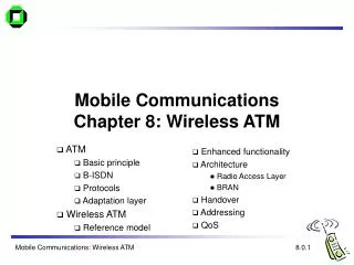
“before” “after” 1149.1 “core” 1149.7 chip 1149.1 IC 1149.7 adapter Adaptation of 1149.1 to 1149.7
IEEE 1149.7 Key Objectives • For Test • Maintain compliance with 1149.1 to preserve the industry test infrastructure • For Applications Debug • Extend/ Advance capability to provide: • Reduced Power Modes • Defined test logic power down • Improved Performance • Shortened multi-chip chains • Glueless “star” configuration • Reduced Pins • Links to “Instrumentation”
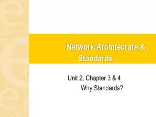
SiP Through-silicon vias die 3 die 2 die 1 TCKC TMSC Star topology for a 3-die SIP
TDI TCK TMS TDO Conventional series topology - highlighting the star wiring for TCK/TMS
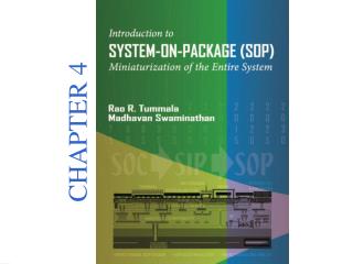
TAP.7 TAP.7 Controller nTRST TCK(C) TMS(C) RSU APU EPU STL TDI(C) TDO(C) PSL Notional view of the 1149.7 architecture Reset and Selection Unit Advanced Protocol Unit Pin Sharing Logic Extended Protocol Unit System Test Logic
Selection Hierarchy • Technology • Where the 1149.7 technology can be placed offline, the TAP.7 signaling can be shared with other technologies • Topology • Where the constituent 1149.7 devices can be placed offline (a function required for T3 and above), the TAP.7 signaling can be shared among any topology branches, whether series, star-2, or star-4 • Adapter (i.e., ADTAPC) • 1149.7 devices comprising a selected topology branch will share TAP.7 signaling and, where the topology branch is star-2 or star-4, a given device may be selected for a given operation • Chip (i.e., CLTAPC) • For a selected ADTAPC, the CLTAPC may be offline and will require selection when it must be operated • Core (i.e., EMTAPC) • For a selected CLTAPC, given EMTAPC(s) of interest may be offline and will require selection when it (they) must be operated
Key Features of the Capability Classes • Six classes of 1149.7 test access ports (TAP.7s), T0 - T5 • Incremental capability, each higher builds upon the lower • Class T0 – foundation • 1149.1 behavior from start-up, even where multiple on-chip TAPs • Class T1 – commands and registers • common debug functions, features to minimize power consumption • Class T2 – scan formats • improved scan performance, optional hot-connection capability • Class T3 – direct addressability • operation in four-wire Series or Star Scan Topology • Class T4 – packetization of scan data (2-pin scan formats) • two-pin or four-pin interface; two-pin operation serializes 1149.1 transactions and provides for higher test clock rates • Class T5 – transport of non-scan data (2-pin mode) • data transfers concurrent with scan, utilization of functions other than scan, and control of TAP.7 pins for custom debug technologies
0 0 0 0 1 Pause-IR Shift-IR Pause-DR Shift-DR Test-Logic-Reset 0 0 1 1 1 Run-Test-Idle Select-DR-Scan Select-IR-Scan 0 0 1 1 Capture-DR Capture-IR 0 0 1 1 a 1 1 Exit1-DR Exit1-IR b 0 0 1 1 0 0 Exit2-DR Exit2-IR 1 1 Update-DR Update-IR 1 0 1 0 T1, TAP FSM trajectories for Zero-Bit Scans
T1, Zero-Bit Scans Create Control Levels Key: • Count the number of Zero-Bit-Scans (ZBS) to change the definition of BYPASS instruction. • Lock control level when the Shift-DR state is reached. 1…. 2…. Lock Control Level at 2. BYPASS IR Register
2nd DR Scan 3rd DR Scan creates Access an EPU scan path 5-bit operand X bits CP2 2 part Command 3 part Command T1, Commands & Registers • Accepted at Control Level 2 • Controller commands are 10-bit values. They consist of 2 consecutive DR scans while the controller is locked at control level 2. • Command Part 1 (CP1) provides the command • Command part 2 (CP2) provides the immediate operand or lower 5 bits of the command • Can create a three-part command • Can send/receive data values other than values embedded in CP2. • Crated by appending an additional DR Scan after the CP1 and CP2 to transport a data value. 1st DR Scan creates 5-bit op-code CP1
T2, Scan Formats • Adds 3 Scan Formats: Change the operation of scan • JSCAN0: Provides compliant IEEE 1149.1 operation • JSCAN1: Provides “Hot” connection and disconnection protection • JSCAN2: Improved performance for Series connected devices. • Write only register is used to specify the scan format • These 3 formats use two features: • Chip Level Bypass • TAP Selection
TCK(C) TMS(C) TDIC TDOC T3, Star-4 Topology
state TCKC nTDI nTDI nTDI TMS TMS TMS TDO TDO TDO TMSC T4, Scan packet serialization, OScan1
TCKC nTDI nTDI nTDI nTDI nTDI nTDI nTDI nTDI nTDI TMSC T4, Scan packet serialization, OScan7 state Shift-xR
T5, Transport • Transport packet type is added to support: • Background Data Transfers (BDX) • Custom Data Transfers (CDX) • When BDX is enabled: • During link IDLE time, instrumentation data is transmitted • Transport packets are attached to the IDLE, PAUSE, or UPDATE states • DTC to target, target to DTC , Bi-Directional or custom transfers • Non-scan data is transferred (ex: instrumentation data) • When CDX is enabled: • Instead of SCAN, an alternate protocol is allowed to use the link during SHIFT-DR TAP states • Transport packets are attached to the IDLE, PAUSE, or UPDATE states • Custom transfers on a clock by clock basis • Non-scan data is transferred
Conclusion • IEEE 1149.7 is a complementary superset of IEEE 1149.1 (JTAG) • Reduced pins and enhanced functionality • Built on the foundation of 1149.1 • rapid adoption possible/ expected • Compatibility for test • Interfacing multiples • cores on SOC • die in SIP • packages for POP • Debug improvements • hot-plug immunity • power management • optimization of scan throughput • access to debug instrumentation • access to custom debug technologies
Further Discussion • Where have you seen 1149.7 chips on your boards? • Where will you see 1149.7 chips on your boards? • Where would you like to see 1149.7 chips on your boards?