Download
1 / 55
550 likes | 800 Vues
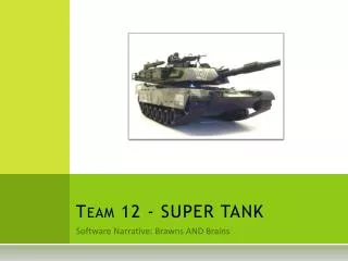
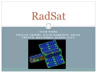
Reconnaissance and Demolition Super Attack Tank A.K.A RADSAT. Jeff Hildebrandt Dylan Lambe Mick Muzac Bradley Raley. About RADSAT. RADSAT is a semi-autonomous tank designed to find, lock onto, and shoot a target specified by its color.

E N D
Reconnaissance and Demolition Super Attack TankA.K.A RADSAT Jeff Hildebrandt Dylan Lambe Mick Muzac Bradley Raley
About RADSAT • RADSAT is a semi-autonomous tank designed to find, lock onto, and shoot a target specified by its color. • The base is an RC tank with sensors mounted on top of it • A camera and air-soft gun (simulated by a laser) are aimed at the target with servos. • RADSAT can be controlled by a laptop as well as voice commands delivered over WiFi. • The user has the option to move the tank manually or have it autonomously roam around. • The user will also be able to view the video stream from the camera within a GUI.
Project Requirements • One battery to power the tank and circuit board for a least 4 hours • Ability to quickly move in a straight line and turn while moving • Sufficient sensors to avoid real-world obstacles • WiFi camera able to relay video information • Ability to aim and fire a laser at the target • Shoot rapidly and accurately • Appropriately sized • Operate in various types of terrain
Infrared Advantages • Sony GP2Y0A02YK infrared is very inexpensive • Not susceptible to interference • Easy to mount and comes with JST connector • Will be used as side sensors to detect side obstructions
Infrared Placement • 20 cm invalid range means sensor needs 20 cm buffer • Duplicate Vo values are impossible
Ultrasonic Advantages • Doesn’t suffer from duplicate Vo problem • Used as front sensor due to range (25ft) • Different modes of operation: 5V > 3.3V • Single speaker Multiple interfaces for measurements • Analog, Serial, Pulse Width
Compass Module • Honeywell HMC6352 • 0.5 degree heading resolution • I2C interface allows for easy integration • Used to facilitate accurate turning • Biggest drawback: prone to magnetic field interference
Camera Selection • Needs to stream a live video feed from RADSAT to the computer screen. • Needs to be in color.
Camera Selection • Find a way to stream a live video feed from RADSAT to the computer screen. • Needs to be in color.
Video Processing • The WiFi camera automatically puts a video stream onto a server. • Using AForge.net video libraries for C# - going to retrieve an MJPEG video stream from the server. • Parse the MJPEG frames into individual JPEG images then convert them to Bitmap. • Each time a new frame is loaded, an event occurs and the program receives a new Bitmap image. • Once the Bitmap image is received the targeting system can occur.
Targeting • The target which RADSAT will be shooting at will be a 10”x10” cardboard cube which will be colored either red, blue, or green. • The program will identify the target using the Bitmap image of the camera’s view. • It can differentiate the target from different objects using color recognition as well as shape recognition.
Color Recognition • A variation of this equation will be applied to every pixel, starting at the top left and moving right until the target is found (This is the equation for finding green). • D = sqrt((R - 0)^2 + (G - 255)^2 + (B - 0)^2), where R represents red within the RGB color scheme, G represents green, and B represents blue. The result D will be compared against a variable. • The larger “D” is then the farther the pixel is from the desired color. • Depending on which color is desired the 255 will replace the zero for either red or blue. • Any pixel that does not meet the specifications will be colored black, making it easier for the user, and program to see exactly what the robot is seeing. There is a button to turn this feature on or off.
Shape Recognition • This function uses • AForge.net blob library. • This library is able to cluster together pixels based on their contrast to the black background. • The program takes these clusters and draws a pink rectangle around them. • They are viewable in Robot Vision Mode
Targeting • This is called after the target has been found. • It will first draw crosshairs at the center point of the target. • The program will check where the target is in relation to the firing point. • It will first move the turret into the correct horizontal position, then when that has been achieved it will move into the correct vertical position both in relation to the firing point.
Phone Server • Creates a server which communicates with the phone via a TCP connection. • It will receive a string and use logic to send the appropriate commands to RADSAT.
Wifi Bee Client • A TCP client which connects to the server on the Wifi bee • It sends character bytes which RADSAT interprets as commands. • This enables back and forth communication between the computer and RADSAT.