Download
1 / 30
300 likes | 493 Vues
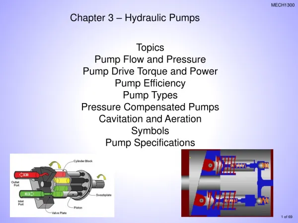
Hydraulic Kit (pump and tank). Pictures from prototype. Hydraulic Kit (pump and tank). Main Characteristics. Size and shape = 5 HP unit. 100 litre tank for all models. Separate power supply. Anti Freeze protection. Q x 1000 x t. V =. x d x Cw x n.

E N D
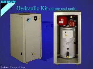
Hydraulic Kit (pump and tank) Pictures from prototype
Hydraulic Kit (pump and tank) Main Characteristics Size and shape = 5 HP unit 100 litre tank for all models Separate power supply Anti Freeze protection
Qx1000 x t V = xdxCw x n 100 litre tank for all models ? The water (glycol) volume should be so big that the time necessary to pull down the water temperature equal to the thermostat difference, is half the time of the anti-recycling time Q = Cooling Capacity at the lowest capacity step (W) t = Anti-recycling time of the compressor (s) = Specific mass of the fluid (kg/m³) d = Thermostat difference (step length) (°C) Cw = Specific heat of the fluid (J/kg°C) (4186 for water) n = Nr of compressors that can work independently
7 6 Thermostat Difference 5 100 litre tank for all models ? Water Out (°C) More Water Less Water Time sec.) The water (glycol) volume should be so big that the time necessary to pull down the water temperature equal to the thermostat difference, is half the time of the anti-recycling time
7 6 Thermostat Difference 5 Anti Recycling Timer 100 litre tank for all models ? Water Out (°C) Water Volume should be selected to cope with the anti-recycling timer of the compressor Compressor On Compressor On Time sec.) 240 The water (glycol) volume should be so big that the time necessary to pull down the water temperature equal to the thermostat difference, is half the time of the anti-recycling time
Only 1 compressor: Example: EUWA20HZ Nominal Cooling Capacity: 42 kW Load: 21 kW Capacity Step: 0 - 100% Thermostat Difference: 1,5 °C Anti Recycling Timer: 240’’ Only half the capacity of the chiller is required… The water (glycol) volume should be so big that the time necessary to pull down the water temperature equal to the thermostat difference, is half the time of the anti-recycling time
For 1 compressor: During On - mode: System will cool down with a capacity of 21 kW During Off - mode: System will heat up with a capacity of - 21 kW The water (glycol) volume should be so big that the time necessary to pull down the water temperature equal to the thermostat difference, is half the time of the anti-recycling time
Thermostat Difference Anti Recycling Timer For 1 compressor: Water Out (°C) Cooling 21 kW Heat Up: 21 kW Time sec.) Compressor Off 240 The water (glycol) volume should be so big that the time necessary to pull down the water temperature equal to the thermostat difference, is half the time of the anti-recycling time
m = * V cwater = 4186 J/kg°C V = 21000 W * 120 s 4186 J/kg°C* 1,5 °C For 1 compressor: Out of the formula Q = m * c * T Q = m / (t) * c * T m = (Q * t) / (c * T) V = 400 l The water (glycol) volume should be so big that the time necessary to pull down the water temperature equal to the thermostat difference, is half the time of the anti-recycling time
For 2 compressors: Example: EUWA20HZ Nominal Cooling Capacity: 42 kW Load: 21 kW Capacity Steps: 0 - 50 - 100% Thermostat Difference: 1,5 °C Anti Recycling Timer: 240’’ The water (glycol) volume should be so big that the time necessary to pull down the water temperature equal to the thermostat difference, is half the time of the anti-recycling time
For 2 compressors: Compressor 1 can operate continuously Compressor 2 is continuously switched off Capacity = Load Constant Temperature is obtained no buffer tank needed The water (glycol) volume should be so big that the time necessary to pull down the water temperature equal to the thermostat difference, is half the time of the anti-recycling time
Thermostat Difference Anti Recycling Timer For 2 compressors: Water Out (°C) Time sec.) Compressor Off 240 The water (glycol) volume should be so big that the time necessary to pull down the water temperature equal to the thermostat difference, is half the time of the anti-recycling time
For 2 compressors: Example: EUWA20HZ Nominal Cooling Capacity: 42 kW Load: 10,5 kW Capacity Steps: 0 - 50 - 100% Thermostat Difference: 1,5 °C Anti Recycling Timer: 240’’ The water (glycol) volume should be so big that the time necessary to pull down the water temperature equal to the thermostat difference, is half the time of the anti-recycling time
On Off 21 kW 10,5 kW Cooling Down 1 2 2 2 0 kW - 10,5 kW Heating Up 1 1 1 21 kW 10,5 kW Cooling Down 2 0 kW - 10,5 kW Heating Up For 2 compressors: Auto lead - lag switching CAPACITY LOAD The water (glycol) volume should be so big that the time necessary to pull down the water temperature equal to the thermostat difference, is half the time of the anti-recycling time
Compressor 1 On Compressor 2 On Thermostat Difference Anti Recycling Timer For 2 compressors: Water Out (°C) Cooling 10,5 kW Heat Up: 10,5 kW Compressor Off Time sec.) 240 The water (glycol) volume should be so big that the time necessary to pull down the water temperature equal to the thermostat difference, is half the time of the anti-recycling time
For 2 compressors: V = 10500 W * 60 s 4186 J/kg°C* 1,5 °C V = 100 l The water (glycol) volume should be so big that the time necessary to pull down the water temperature equal to the thermostat difference, is half the time of the anti-recycling time
10 + 10 + 10 The max. water volume is determined by the capacity of a 10 Hp compressor
Hydraulic Module Model Names • EHMC 10 AV1 ( 5 10 HP ) • EHMC 15 AV1 (15 HP ) • EHMC 30 AV1 ( 20 30 HP)
Outlook 1284 mm 635 mm 724 mm Pictures from prototype
Outlook Water Outlet Modification to service panels : Water Inlet Other Cover ! Pictures from prototype
Outlook STANDARD MODEL 10 m H2O Pictures from prototype
Outlook Air Purge Pressure port (On the same side as the regulating valve) Pictures from prototype
Outlook Pressure regulating Shut-off valve Safety Valve Pressure Gauge Pressure port Pictures from prototype
Outlook Water INLET and Shut-Off valve For Freeze-up Protection Drain Plug Pictures from prototype
Outlook Main Switch Manual - O - Auto Pictures from prototype
Outlook Thermal Protector Pump Relay Field Wiring Standard : 6 Core Pictures from prototype
Compatibility FOR 15 MODELS ! • EHMC 10 AV1 • EUWA 5 / 8 /10 H (Z) W1 / T1 • EUWY 5 / 8 10 H W1 EUWA 5 / 8 /10 H (Z) W1 / T1 EUWA 5 / 8 /10 H (Z) W1 / T1 EUWA 5 / 8 /10 H (Z) W1 / T1 EUWY 5 / 8 10 H W1 • EHMC 15 AV1 FOR 5 MODELS ! • EUWA 15 H (Z) W1 / T1 • EUWY 15 H W1 • EHMC 30 AV1 FOR 15 MODELS ! • EUWA 20 / 25 / 30 H (Z) W1 / T1 • EUWY 20 / 25 / 30 H W1
Installation Alongside the chiller or remotely A drain pan enables an indoor installation under all conditions Water inlet is at the same height as the chiller outlet Power supply possible via the chiller Easy hydraulic balancing via pressure regulating valve
Options • 010 • Freeze-Up Protection ( 200 Watt Heater ) = Standard • 070 • High Static Pump (30 m H2O)